B4R Question Capacitance-to-Digital Converter - any solution ?

peacemaker

Expert
Licensed User
Longtime User
Hi, All

Maybe anyone tried to make the capacitor measurement with B4R ?
Starting several picoFarads...
 

derez

Expert
Licensed User
Longtime User
Explanation of the electronics involved:
When you have a circuit like this (called RC circuit):
1650011621096.png


Starting to load the capacitor when connecting switch 1, the voltage on the capacitor is like this graph:

1650011644681.png


The voltage function is this:
1650011682862.png

(
1650012124962.png
is the power supply/battery voltage)
From this you get: C = -t/(R*ln(1-Vc/
1650011928179.png
))

as is set in the code of the library mentioned above:

capacitance = -(float)t * 1000.0 / _rPullup / log(1.0 - (float)val / (float)_maxAdcValue);

So you can build your own device on any board, taking into account the specific Vcc and selecting R and loading time so not to reach max loading, without the library, using B4R code only.
 

Attachments

  • 1650011480456.png
    1650011480456.png
    6.3 KB · Views: 86
  • 1650011575052.png
    1650011575052.png
    10.6 KB · Views: 98
Last edited:
Upvote 0

peacemaker

Expert
Licensed User
Longtime User
Yes, thanks for the theory.
But as i can understand, for ESP8266 it needs to get info about the internal _rPullup. And Vc on the ADC pin must be scaled to be under 1 V (but power supply from ports is of 3.3 V).
And moreover, it's most interesting now the small capacitors that needs to know internal _inCapToGnd:
B4X:
//Low value capacitor - calculate result
        capacitance = (float)val * _inCapToGnd / (float)(max(_maxAdcValue - val, 1));


I'll try to use "Qtouch" method.
 
Last edited:
Upvote 0

derez

Expert
Licensed User
Longtime User
I had to play a little and worked out a working example .
I used a 4.7 Kohm resistor and the following capacitors: 0.1, 1, 2.2, 3.3, 10, 22, 33, 47, 100 and 220 microfarad.
1650189323410.png

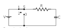
Connections: resistor between pin7 and pin A0, from pin A0 to the plus side of a capacitor, the negatives of the capacitors are to ground.
pin7 supplies the full voltage of 3.3v when turned on, ground when off.
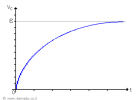
pi A0 measures the voltage on the capacitor after t time from voltage on.

The results were not consistent so I had to introduce a calibration function.

B4X:
Sub Process_Globals
    Public Serial1 As Serial
    Private pin7 As Pin
    Private tmr As Timer
    Private d1 As D1Pins
    Private sense As Pin
    Private cval As Double
    Private sval As Int
    Private cal As Double 
    Private t As Int = 13000
End Sub

Private Sub AppStart
    Serial1.Initialize(115200)
    Log("AppStart")

    pin7.Initialize(d1.D7,pin7.MODE_OUTPUT)
    pin7.DigitalWrite(False)
    sense.Initialize(sense.A0,sense.MODE_INPUT)
    tmr.Initialize("tmr_Tick",60000)
    tmr.Enabled = True
    Delay(5000)
    tmr_tick
End Sub

Sub tmr_tick

    pin7.DigitalWrite(False)
    Delay(1000)
    t = 13000

    pin7.DigitalWrite(True)
    DelayMicroseconds(t)
    sval = sense.AnalogRead
    Log(t, "  ",sval)
    get_cal
    If t < 13000 Then
        pin7.DigitalWrite(False)
        Delay(1000)
        pin7.DigitalWrite(True)
        Log(t)
        DelayMicroseconds(t)
        sval = sense.AnalogRead
        Log(sval)
    End If
    cval = -t / 4700 / Logarithm(1.0 - sval*cal/1023,cE )

    Log("c = " ,cval , "  microfarad")
    pin7.DigitalWrite(False)
    Log("*******************")
    
End Sub

Sub get_cal
    Select True
        Case sval < 30
            cal = 0.475
        Case sval < 50
            cal = 0.68
        Case sval < 320
            cal = 0.8
        Case sval < 700
            cal = 0.895
        Case Else
            cal = 0.94
    End Select
    
    If sval > 1015 Then
        t = 500
        cal = 0.7
    End If
    Log("cal= " , cal, "  t= ", t)
End Sub

To measure connect the specific capacitor and either reset the card or wait for the timer tick.
I didn't check other values of capacitors, they will probably require some more calibration values.
 
Last edited:
Upvote 0

peacemaker

Expert
Licensed User
Longtime User
Arduino native boards - no problem for the task, many samples can be found.
Trouble is as usual if to try ESP8266 :)
The task is to measure 1......200 pF.
I have tried manually QTouch method of Atmel, but not stable result.
And trying now this lib: https://github.com/PaulStoffregen/CapacitiveSensor

Code:
  send ESP pin         +-----------+       
  ---------------------|  100 kOhm |---------
                       +-----------+        |
  receiver ESP pin     +-----------+        |
  ---------------------|  1 kOhm   ----------
                       +-----------+        |
                                        --------
                                        --------
                                            |
               test capacitor  1 ... 200 pF |
                                            |
                                            |
                                          -----
                                           ---
                                            -


And it seems, the sender pin can be only GPIO4 (SCL) = D2 of NodeMCU.
Code::
Private Sub Process_Globals
    'These global variables will be declared once when the application starts.
    'Public variables can be accessed from all modules.
    Private tim As Timer
    Private Measured As Long
    Private isMeasuring As Boolean
End Sub

Sub Setup
    tim.Initialize("tim_Tick", 1000)
    tim.Enabled = True    'start measuring loop
End Sub

Private Sub tim_Tick
If isMeasuring = False Then
    isMeasuring = True
    RunNative("measure_cap", 30)  'the qty of attempts as parameter
    Log("Measured = ", Measured)
    isMeasuring = False
End If
End Sub

'GPIO4 = D2 of NodeMCU (SCL): send pin (100K resistor from port to the cap) - it'simportant powerful pin of ESC8266 !
'GPIO0 = D3 of NodeMCU: capacitance sensor input (1K protection resistor from port to the cap)
#if C
#include <CapacitiveSensor.h>
void measure_cap (B4R::Object* o) {
CapacitiveSensor cs_4_0 = CapacitiveSensor(4,0);
cs_4_0.set_CS_AutocaL_Millis(0xFFFFFFFF);     // turn off autocalibrate
long capres = cs_4_0.capacitiveSensor(o->toULong());
b4r_capsensor::_measured = capres;
}
#End if

Now the output is error = -2. Debugging...
 
Last edited:
Upvote 0

peacemaker

Expert
Licensed User
Longtime User
This is ESP8266...
Yes, but if it needs the smallest, cheapest, low consuming, with WiFi and ... with lots of developed\collected code - it worth to use...

Measurement is solved:

B4X:
'Capacitance measure module (tested with ESP8266 NodeMCU v.1)
'©2022 Vlad Pomelov aka Peacemaker v.0.401
'compile with 160 MHz ESP8266 clock setting !

Private Sub Process_Globals
    'These global variables will be declared once when the application starts.
    'Public variables can be accessed from all modules.
    Private Port_PinInput As Byte = 0    'input pin GPIO0 = D3 of NodeMCU: (sensor input), 390 kOhm
    Private Port_PinOutput As Byte = 4    'output pin GPIO4 = D2 of NodeMCU: (output charging port), 1 kOhm
    Private PinInput, PinOutput As Pin
    Private tim As Timer
    Private isMeasuring As Boolean

End Sub

Sub Setup
    Delay(100)
    PinInput.Initialize(Port_PinInput, PinInput.MODE_OUTPUT)
    PinInput.DigitalWrite(False)
    PinOutput.Initialize(Port_PinOutput, PinOutput.MODE_OUTPUT)
    PinOutput.DigitalWrite(False)
    tim.Initialize("tim_Tick", 1000)
    tim.Enabled = True    'start measuring loop
End Sub

Private Sub tim_Tick
If isMeasuring = False Then
    Dim Cycles As Long = Measure
    Log("Measured = ", Cycles)
End If
End Sub

'measure the capacitance
Private Sub Measure As ULong
    If isMeasuring Then
        'Busy. Ignore measurement
        Return -1
    End If
    isMeasuring = True
    Dim resValue As Long
 
    PinInput.Mode = PinInput.MODE_INPUT    'prepare to check the charging status
    'charging start
    PinOutput.DigitalWrite(True)
    PinOutput.Mode = PinOutput.MODE_OUTPUT
 
    'wait for the full charge
    Do While PinInput.DigitalRead = False
        RunNative("yld", Null)
    Loop
    Delay(1000)    'charge a bit more for sure
    PinOutput.Mode = PinOutput.MODE_INPUT  'stop charging
    'start discharging
    PinInput.Mode = PinInput.MODE_OUTPUT
    PinInput.DigitalWrite(False)
 
 
    Do While PinOutput.DigitalRead    'wait for discharge
        resValue = resValue + 1    'calculate time until the cap is got discharged
    Loop
 
    'discharge all
    PinInput.Initialize(Port_PinInput, PinInput.MODE_OUTPUT)
    PinInput.DigitalWrite(False)
    PinOutput.Initialize(Port_PinOutput, PinOutput.MODE_OUTPUT)
    PinOutput.DigitalWrite(False)
    Delay(1000)    'discharge a bit more for sure
    isMeasuring = False
    Return resValue
End Sub

Private Sub DelayMicrosec(microseconds As UInt)
    Dim Start As ULong = Micros
    Do While True
        Dim Check As ULong = Micros
        If Check > microseconds + Start Then
            Exit
        End If
        If Check Mod 100 = 0 Then
            RunNative("yld", Null)
        End If
    Loop
End Sub

#if C
void yld(B4R::Object* o){
    yield();
}
#End If

TempDownload.png

1000 pF is measured as 726.
6.8 pF is not detected, measured as 0.
22 pF is measured as 1...10, not stable.
22 + 6.8 = 28.8 pF is measured as 5...24, mostly 24.
It's all already with 160 MHz ESP8266 clock setting, not 80 MHz.
 
Last edited:
Upvote 0
Top