B4R Question Trouble with Wemos D1 Mini

Hbtr

Member
Hello there,

I never worked with electronics or with programming, but few months ago I accepted the challenge, from my 8 years old son, to study and after teach him.
I already did some minor projects that worked very fine and we are enjoying each step.
My last project, perhaps, is becoming the greater challenge until then. Design a Smart Fan, with a button for switching between speeds, motorized oscillating system, IR control and, after all the previous items are done, voice control by alexa.
I was able to gain success on all the items (voice control is a bonus that I will pursue after the prime design is done), and the Breadboard version was fully functional. So I decided for a new step, PCB design, and everything worked like a charm (at least that is what I believe). Had minor tweaks to be done on the PCB, but mainly it was fine.
I was powering all the system using the USB port of the Wemos, in all the versions of the project, from the breadboard version up to the PCB version, and everything was fine. On the PCB version I included a 5V Hilink power source for the system, but all the primary tests were being done by the Wemos USB port.
But, when I finally powered the system with the Hilink... weird stuff happened.
It turned on. The controls worked, the leds lighted up as it should. The buzzer sounded the correct "beeps". But the relays weren't switching.
The design uses three relays where one is for each speed of the fan. It works, and I did several tests with the breadboard version, and everything was fine. The PCB version works also, and all the relays switch according to the design... but only when powered by the USB port of the Wemos. When it's powered by the HILINK, the remain silent.
double checked all the PCB tracks. The diagram also. Used a external spare hilink to power the system, inserting the 5v directly to the "Vin" of the wemos D1, and the problem persists.
Now I am out of options. How I am a Noob, I am sure that something simple has not been seen by me, but more experienced eyes may detect.
So here I am begging for help.
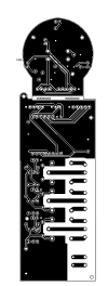
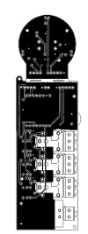
Below is the diagram of the design and the PCB board. If you need more material to analyse, let me know.
 

Attachments

  • PCB_PCB_Ventilador Inteligente - V 2.5_Bottom Layer.png
    PCB_PCB_Ventilador Inteligente - V 2.5_Bottom Layer.png
    23.4 KB · Views: 182
  • PCB_PCB_Ventilador Inteligente - V 2.5_Top Layer.png
    PCB_PCB_Ventilador Inteligente - V 2.5_Top Layer.png
    31.1 KB · Views: 172
  • Schematic_Ventilador Inteligente - V 2.5_2022-06-01.pdf
    100.6 KB · Views: 173

f0raster0

Well-Known Member
Licensed User
Longtime User
But, when I finally powered the system with the Hilink... weird stuff happened.
It turned on. The controls worked, the leds lighted up as it should. The buzzer sounded the correct "beeps". But the relays weren't switching.
The design uses three relays where one is for each speed of the fan. It works, and I did several tests with the breadboard version, and everything was fine. The PCB version works also, and all the relays switch according to the design... but only when powered by the USB port of the Wemos. When it's powered by the HILINK, the remain silent.
double checked all the PCB tracks. The diagram also. Used a external spare hilink to power the system, inserting the 5v directly to the "Vin" of the wemos D1, and the problem persists.
better if you can upload the final version of your schematic, the current one look like not finished, for example, better add the optional capacitor (HLK-PM01 link)
HLK-PM01.jpg


have you tried to remove the HLK-PM01 and apply direct +5V from an external power supply ? (no to Wemos D1 Mini)

HLK-PM01_1.jpg


Edit:
I have the feeling that you are missing a GND connection when using HLK-PM01, that could explain why it works using the Wemos D1 Mini
 
Last edited:
Upvote 0

Hbtr

Member
better if you can upload the final version of your schematic, the current one look like not finished, for example, better add the optional capacitor (HLK-PM01 link)
View attachment 129878

have you tried to remove the HLK-PM01 and apply direct +5V from an external power supply ? (no to Wemos D1 Mini)

View attachment 129879

Edit:
I have the feeling that you are missing a GND connection when using HLK-PM01, that could explain why it works using the Wemos D1 Mini
Thanks for your reply and attention.
Somehow the schematic didn't open correctly on your machine. Will place a bitmap version.
About the capacitor, I considered something like that, but checking the hlk-pm01, I noticed that it is "sold" as a "all-in-one" solution, where the capacitor would already exist inside his circuitry. But I lick check that. Thanks.
Yes, I did supply the 5v by another external power source. I used another hilink (just in case there was any interference on the tracks of the PCB or that the soldered hilink was defective) and I also used an arduino to power the D1 on the Vin pin.
What I did yesterday, and worked, but I wished to understand better, was... I used the multimeter on several tracks of the PCB, when the system was powered up with the USB por on the Wemos D1, and after I repeated the readings when the system was powered by the HiLink, and noticed that the was a small difference of 0.3 volts (USB port - 4.7 volts, hilink - 5 volts). So then I decided to place a 50 ohms resistor right after the DC output of the hilink (before it feeds the system), and the relays began to switch normaly.
I confess that this "hypersensitivity" of the design, seems weird to me. I expected it to be more robust. That's why I still wish to understand what happened. ;-)
1654177118446.png
 
Upvote 0

f0raster0

Well-Known Member
Licensed User
Longtime User
What I did yesterday, and worked, but I wished to understand better, was... I used the multimeter on several tracks of the PCB, when the system was powered up with the USB por on the Wemos D1, and after I repeated the readings when the system was powered by the HiLink, and noticed that the was a small difference of 0.3 volts (USB port - 4.7 volts, hilink - 5 volts). So then I decided to place a 50 ohms resistor right after the DC output of the hilink (before it feeds the system), and the relays began to switch normaly.
could be because Opto is not working properly.. try to increase 1K or just connect the opto pin4 to +5V.
check the value in pin 4 of the relay when on and off. Maybe it's not "low"/"high" when the circuit is using HLK-PM01

Edit: But don't know, it is up to you: "if it works, don't touch" :)
 
Upvote 0

Hbtr

Member
could be because Opto is not working properly.. try to increase 1K or just connect the opto pin4 to +5V.
check the value in pin 4 of the relay when on and off. Maybe it's not "low"/"high" when the circuit is using HLK-PM01

Edit: But don't know, it is up to you: "if it works, don't touch" :)
I found the problem! But it doesn't explain all the weird behavior of the system.
How I said before, the resistor solved the problem, but it didn't explain why it worked when the ESP was powered by the USB, and didn't work when it was powered by the Vin. So I dug deeper.
The problem was so simple that I am shamed to report here... one of the transistors was poorly soldered. Just that! When I fixed the problem, all the system began to work properly, and the 50ohms resistor wasn't needed anymore.
I just wanted to understand why it worked normally when powered by USB and not when powered by Vin. If the problem was only the transistor, why it didn't bug the working of the system when powered by USB also?
Thanks for the help. ;-)
 
Upvote 0

Hbtr

Member
Solved the problem with the switching of the relays. The resistor and the better soldering solved it. But now I have another problem.
The design has an IR receiver. On the breadboard, it worked fine, or at least it seemed to. But now on the PCB, when the IR is connected to the board, strange behavior happens.
The relay doesn't hold the position. It switches, but after a few milliseconds, it loses its position. The wemos believes that it's ok, because it shows that the relay is on, but in fact, it isn't. Seems like a power problem and not a logical one. And as I said, it happens only when I plug the IR. If I remove the IR, everything goes fine.
I really am not liking this temperamental behavior of the system. In previous designs of other pieces of equipment, I enjoyed the precision of the "digital". But now, everything seems so... analogical.
 
Upvote 0

Cableguy

Expert
Licensed User
Longtime User
Your thread title is misleading to say the least.
Your problème Nevers was the board itself... And now that it seems to have been solved, you should changé thé title accordingly
 
Upvote 0

Hbtr

Member
Your thread title is misleading to say the least.
Your problème Nevers was the board itself... And now that it seems to have been solved, you should changé thé title accordingly
Well, I didn't know what was causing the original problem, and how the design was done to work with the wemos D1 mini, I considered that it was OK to place it on the topic. In fact, the trouble that persists, if caused by any interference or conflict on the ports, would point to the direction that it's related to the ESP board. Not a problem of the board itself, but on my design using the board.
 
Upvote 0
Top