B4R Tutorial B4R Vibration Sensor (shake switch)

So long that I haven't played with B4R ! Today I want to test a vibration sensor (it's on a closed case yet)
The sensor signals when a sensor shake happens. It's a simple sensor (detected/not detected) and a simple circuit.
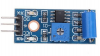
Sensor

upload_2019-10-25_11-38-40.png


Circuit

upload_2019-10-25_11-35-46.png


Code:

B4X:
Sub Process_Globals
    Public Serial1 As Serial
    Private ip,op As Pin
    Public timepassed,timeactual As ULong
    
End Sub

Private Sub AppStart
    Serial1.Initialize(115200)
    Log("AppStart")
    ip.Initialize (6, ip.MODE_INPUT)
    op.Initialize (7, op.MODE_OUTPUT)
    op.DigitalWrite(False)
    ip.AddListener("Change_state")     
End Sub

Sub Change_state (State As Boolean)
    timeactual=Millis
  
    Select Case State
        Case True           
            Log("state: Detected")
            Do While timeactual-timepassed < 400
                timeactual=Millis
            Loop
            op.DigitalWrite(Not(State))
        Case False
            Log("state: Not Detected")
            op.DigitalWrite(Not(State))           
    End Select
    
    timepassed=Millis   
End Sub
 

Attachments

  • upload_2019-10-25_11-37-52.png
    upload_2019-10-25_11-37-52.png
    162.9 KB · Views: 341
  • upload_2019-10-25_11-38-27.png
    upload_2019-10-25_11-38-27.png
    162.9 KB · Views: 319

hatzisn

Well-Known Member
Licensed User
Longtime User
Hi Inakigram, did you miss a drop down resistance in the input of the led?
 
Last edited:

hatzisn

Well-Known Member
Licensed User
Longtime User
Yeap, kind of itching a plate with a fork. :) Actually I asked out of lack of knowledge. I though that Arduino UNO was 3.3V and this had something to do with the absence of the resistance. Wikipedia and Google cleared any doubts.
 

Cableguy

Expert
Licensed User
Longtime User
The resistor is usually placed to force a limited current through the LED, otherwise it will take as much current as the pin can provide. However, some Arduino pins are quite limited in current provided, so the RISC of blowing the LED is also very dim, but it will undoubtedly decrease its life expectancy!
 
Last edited:

hatzisn

Well-Known Member
Licensed User
Longtime User
Getting the opportunity from the previous post I would like to ask something that always (since July that I started practically dealing with electronics because theoretically I have done this in the past) confused me.
Since P = R*I^2 the power that consumes the resistor, in order to keep this under the critical value (value in which the resistor is burnt) for each resistor we have to add more resistors in series. Right? So we have to play with two variables (total R and desired current=f(total R) ) to keep the power consumed in each resistance under the critical value. Thus the current that goes in the LED has to be in a defined range which by itself defines the range of total R and the number of resistors to use in order to be under the critical P limit for each. Am I correct?
 
Last edited:

Cableguy

Expert
Licensed User
Longtime User
If you place two (or more) resistors in series their values are added, but the max power is of the lowest power of the individual resistors. i.e: you place 2 X 1w resistors with a .5w one, the resulting maxP will be .5w
If you place 2 resistors in parallel then it's a completely different ball game. There's a formula for calculating the resulting resistance value... But Power wise, basically, to make it simple, you add the power of each individual resistors. i.e: 2x 10kohm 0.5w in parallel result is a 5kohm 1w value
 

Cableguy

Expert
Licensed User
Longtime User
But, in order to calculate a LED resistor value, is quite simple:
You need to know the pins output voltage and the optimal current for the tips of led you are using, typical values are between 15mA and 25mA.
Then we take ohm's law, I = V/R... The rest is math and finding the nearest standard resistors value
 

hatzisn

Well-Known Member
Licensed User
Longtime User
Hi Cableguy. I am familiar both with Ohm's law as well as the total resistance calculations law as I took some Electronics classes in the University. I am totally confused though with the Power consumption as my calculations tell me different things. See the following picture (the 1st line is P1max < P2max and the correct formula in the last line is P(all)=P1+P1+P2 as P2=V^2/8R is the consumption in R1 and P1=V^2/16R is the consumption in R2 & R3) :
20191025_190058_2.jpg


The three resistors share a common current but as I calculate the consumption is different according to the resistance value. Am I missing something here because you say that the max power is equal to the lowest power?
 
Last edited:

Cableguy

Expert
Licensed User
Longtime User
we are talking about different things, I think...
The Power value of a resistor relates to the Current x Voltage that goes through it, so if you have a 10W resistor, and aply a 10V tension trough it, you can achieve a max through current of 1AMP...
I guess the Power you are calculating is the power dissipation or power loss of the resistor..
 

hatzisn

Well-Known Member
Licensed User
Longtime User
You are absolutely right. I was lost in the translation.
 

hatzisn

Well-Known Member
Licensed User
Longtime User
It's been three days and no answer. :) Obviously my intention to get an answer was lost in the previous post. ;) Well, is what I suggested in post#6 correct about power dissipation?
 

inakigarm

Well-Known Member
Licensed User
Longtime User
It's been three days and no answer. :) Obviously my intention to get an answer was lost in the previous post. ;) Well, is what I suggested in post#6 correct about power dissipation?
You can test the desired R values on http://ledcalc.com/ or similar pages (examples of common drop V values and mA on leds) ; maybe this question is out of the Post scope and could be forwarded on a new post.
 
Top