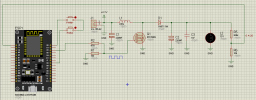
Create a Boost (step-up) converter controlled by an ESP8266 (Wemos D1 Mini), capable of increasing a low input voltage (e.g., 3.1V) to a regulated output voltage (e.g., 14.5V), using PWM (pulse-width modulation).
200µH Inductor
MOSFET (e.g., IRF540 or IRLZ44N)
Fast-recovery Schottky diode
Electrolytic capacitor (at the output)
Voltage divider resistors (built-in on Wemos A0)
Load (e.g., 24V 5W lamp or other)
Power source: 3.1V (e.g., batteries)
The inductor stores energy when the MOSFET turns on and releases it to the load when the MOSFET turns off.
The output voltage is fed through a voltage divider and read by the ESP8266’s ADC (A0 pin).
The ADC reading is converted to the actual voltage based on a calibration factor (adjusted using a multimeter).
The software compares the output voltage with the desired setpoint (e.g., 14.5V).
If the voltage is below the setpoint, the PWM is increased to deliver more energy to the inductor.
If it's above the setpoint, the PWM is reduced.
Everything is done in real time by a timer that checks and adjusts the PWM every 500ms.

 www.instagram.com
Components Used:
ESP8266 (Wemos D1 Mini)200µH Inductor
MOSFET (e.g., IRF540 or IRLZ44N)
Fast-recovery Schottky diode
Electrolytic capacitor (at the output)
Voltage divider resistors (built-in on Wemos A0)
Load (e.g., 24V 5W lamp or other)
Power source: 3.1V (e.g., batteries)
How It Works:
The ESP8266 generates a PWM signal on pin D2 to control the MOSFET.The inductor stores energy when the MOSFET turns on and releases it to the load when the MOSFET turns off.
The output voltage is fed through a voltage divider and read by the ESP8266’s ADC (A0 pin).
The ADC reading is converted to the actual voltage based on a calibration factor (adjusted using a multimeter).
The software compares the output voltage with the desired setpoint (e.g., 14.5V).
If the voltage is below the setpoint, the PWM is increased to deliver more energy to the inductor.
If it's above the setpoint, the PWM is reduced.
Everything is done in real time by a timer that checks and adjusts the PWM every 500ms.
B4R:
Sub Process_Globals
    Public Serial1 As Serial
    Public Adc As Pin                 ' Pino ADC (A0)
    Public TimerADC As Timer         ' Temporizador para ler a tensão
    Private esp As ESP8266extras
    Private ESPin As D1Pins

    Public PWM As Pin                ' Pino de saída PWM (D2)
    Public Pwm_freq As Float = 12000 ' Frequência do PWM em Hz
    Public Valor As UInt = 505       ' Valor de PWM entre 0 e 1023
'    Valor = 512 ' ~50%
'    Valor = 480 ' ~47%
'    Valor = 440 ' ~43%
'    Valor = 400 ' ~39%
End Sub

Private Sub AppStart
    Serial1.Initialize(115200)
    Delay(1000)
    Log("Iniciando Conversor Boost...")

    ' Configura a frequência do PWM
    esp.AnalogWriteFreq(Pwm_freq)

    ' Configura PWM
    PWM.Initialize(ESPin.D2, PWM.MODE_OUTPUT)
    PWM.DigitalWrite(False)
    PWM.AnalogWrite(Valor) ' Inicializa com duty definido

    ' Inicializa ADC
    Adc.Initialize(Adc.A0, Adc.MODE_INPUT)

    ' Timer para leitura da tensão
    TimerADC.Initialize("TimerADC_Tick", 500) ' A cada 500ms
    TimerADC.Enabled = True
End Sub

Sub TimerADC_Tick
    Dim Soma As Float = 0
    Dim N As Int = 10 ' Número de leituras para média

    ' Faz 10 leituras e soma os valores
    For i = 0 To N - 1
        Soma = Soma + Adc.AnalogRead
        Delay(10) ' Pequeno atraso para estabilizar
    Next

    ' Calcula a média das leituras
    Dim Leitura As Float = Soma / N
    Dim Voltagem As Float = Leitura * (20 / 1024) + 10.50 ' Ajuste da diferença
    Log("Voltagem de Saida: ", Voltagem, " V")


    PWM.AnalogWrite(Valor)
    Log("PWM: ", Valor)
End Sub
César Morisco on Instagram: "#projetos #eletronicos #Conversor"
4 likes, 0 comments - cesar_morisco on April 5, 2025: "#projetos #eletronicos #Conversor".
www.instagram.com