B4R v1.20 added support for ESP8266 modules. ESP8266 is a great module for IoT solutions. For a few dollars you get a powerful microcontroller with built-in support for wifi.
I recommend to develop with a board that includes a USB to serial converter.
Configuration
rESP8266WiFi - Similar to rEthernet library. It includes the following types:
Example of a socket connection (depends on rESP8266WiFi and rRandomAccessFile).
Note that it requires B4R v1.50+ as it uses the new B4RSerializator feature:
B4J code (project is attached):
Make sure to update the ESP8266 ip address, it will be printed in the logs.
Notes
- Under the hood there are many differences between ESP8266 and the Arduinos. One of the differences which can be relevant for developers is that the network stream is buffered. If you are writing directly to WiFiClient.Stream then you will need to call WiFiClient.Stream.Flush or the data will not be sent. This is not required when writing with AsyncStreams (which is the recommended way).
- Check the board voltage. The WeMos board is 3.3v.
- Not all libraries are supported.
Example of configuring the ESP8266 wifi by connecting to its access point: https://www.b4x.com/android/forum/threads/esp8266-wifi-remote-configuration.68596/
I recommend to develop with a board that includes a USB to serial converter.
Configuration
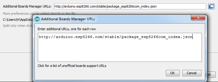
- Open Arduino IDE - File - Preferences and add the following URL: http://arduino.esp8266.com/stable/package_esp8266com_index.json
- In Arduino IDE -> Tools - Board - Boards Manager. Search for esp and install esp8266 by ESP8266 community.
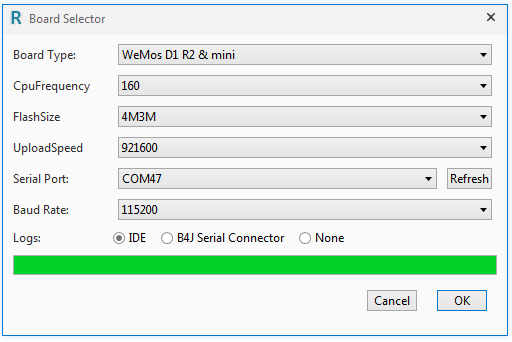
- Open the boards selector in B4R and select the board type (select the highest UploadSpeed):
rESP8266WiFi - Similar to rEthernet library. It includes the following types:
- ESP8266WiFi - Responsible for connecting or creating the wireless network.
- WiFiSocket - Equivalent to EthernetSocket.
- WiFiServerSocket - Equivalent to EthernetServerSocket.
- WiFiUDP - Equivalent to EthernetUDP
- ESP8266 - Currently includes a single method that restarts the board.
- D1Pins - Maps the pins of WeMos boards.
Example of a socket connection (depends on rESP8266WiFi and rRandomAccessFile).
Note that it requires B4R v1.50+ as it uses the new B4RSerializator feature:
B4X:
Sub Process_Globals
  Public Serial1 As Serial
  Private wifi As ESP8266WiFi
  Private server As WiFiServerSocket
  Private astream As AsyncStreams
  Private timer1 As Timer
  Private ser As B4RSerializator
End Sub

Private Sub AppStart
  Serial1.Initialize(115200)
  Log("AppStart")
  'ScanNetworks
  If wifi.Connect("dlink") Then 'change to your network SSID (use Connect2 if a password is required).
  Log("Connected to wireless network.")
    Log("My ip: ", wifi.LocalIp)
  Else
  Log("Failed to connect.")
  Return
  End If
  timer1.Initialize("timer1_Tick", 1000)
  timer1.Enabled = True
  server.Initialize(51042, "server_NewConnection")
  server.Listen
End Sub

Sub Server_NewConnection (NewSocket As WiFiSocket)
   Log("Client connected")
    astream.Initialize(NewSocket.Stream, "astream_NewData", "astream_Error")
End Sub

Sub Timer1_Tick
  If server.Socket.Connected Then
  astream.Write(ser.ConvertArrayToBytes(Array("Time here is: ", Millis)))
  End If
End Sub


Sub AStream_NewData (Buffer() As Byte)
   Dim be(10) As Object
   Dim data() As Object = ser.ConvertBytesToArray(Buffer, be)
   Log("Received:")
   For Each o As Object In data
     Log(o)
   Next
End Sub

Sub AStream_Error
  Log("Error")
  server.Listen
End Sub

Private Sub ScanNetworks 'ignore
  Dim numberOfNetworks As Byte = wifi.Scan
  Log("Found: ", numberOfNetworks, " networks.")
  For i = 0 To numberOfNetworks - 1
  Log(wifi.ScannedSSID(i))
  Next
End Sub
B4J code (project is attached):
Make sure to update the ESP8266 ip address, it will be printed in the logs.
B4X:
Sub Process_Globals
   Private socket As Socket
   Private astream As AsyncStreams
   Private ser As B4RSerializator
End Sub

Sub AppStart (Args() As String)
   socket.Initialize("socket")
   socket.Connect("192.168.0.43", 51042, 0)
   ser.Initialize
   StartMessageLoop
End Sub

Sub Socket_Connected (Successful As Boolean)
   If Successful Then
     If astream.IsInitialized Then astream.Close
     astream.Initialize(socket.InputStream, socket.OutputStream, "astream")
   End If
End Sub

Sub AStream_NewData (Buffer() As Byte)
   Dim data() As Object = ser.ConvertBytesToArray(Buffer)
   Log("Received:")
   For Each o As Object In data
     Log(o)
   Next
   astream.Write(ser.ConvertArrayToBytes(Array("Thank you!", "Time here: ", DateTime.Time(DateTime.Now))))
End Sub

Sub AStream_Error
  Log("Error")
End Sub

Sub AStream_Terminated
  Log("Terminated")
End Sub
Notes
- Under the hood there are many differences between ESP8266 and the Arduinos. One of the differences which can be relevant for developers is that the network stream is buffered. If you are writing directly to WiFiClient.Stream then you will need to call WiFiClient.Stream.Flush or the data will not be sent. This is not required when writing with AsyncStreams (which is the recommended way).
- Check the board voltage. The WeMos board is 3.3v.
- Not all libraries are supported.
Example of configuring the ESP8266 wifi by connecting to its access point: https://www.b4x.com/android/forum/threads/esp8266-wifi-remote-configuration.68596/
Attachments
Last edited:
")