Hi,
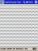
This application uses the ImageButton control to test as much of the
PDA's Touch Screen area as possible. I created an array of the smallest
sized ImageButtons that I could. The array is 12 buttons across by 13
buttons down the screen or 13 rows by 12 columns for a total of 156
ImageButtons on a 240 x 320 PDA screen.
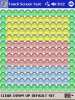
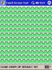
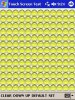
You simply press each ImageButton and it will change color. Once you
have pressed all 156 buttons you know if all areas of the PDA's Touch
Screen are working properly. It will give you a good idea if all areas of
the Touch Screen can respond to a Stylus pressing down upon it and
being released.
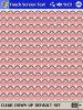
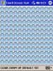
The ImageButton's "down" and "up" events are used. When a button is
pressed the ImageButton will change to a "red" color. When a pressed
ImageButton is released it will change to a "green" color. An ImageButton
that has not been pressed yet will be a "clear" color.
You can change the color of the ImageButton's "down" and "up" states.
It is interesting to know that you can have up to 156 ImageButtons on
one Form on a 240 x 320 PDA screen.
The file "Tscreen.sbp" is the Basic4ppc source code file for the program.
The file "Tst1.JPG" is a screenshot of the program.
The file "Tst2.JPG" is a screenshot of the program.
The file "Tst3.JPG" is a screenshot of the program.
The file "Tst4.JPG" is a screenshot of the program.
The file "Tst5.JPG" is a screenshot of the program.
The file "Tst6.JPG" is a screenshot of the program.
The file "tscreenzip.zip" is the zipped up ARMV4 (.CAB) installation file.
This application uses the ImageButton control to test as much of the
PDA's Touch Screen area as possible. I created an array of the smallest
sized ImageButtons that I could. The array is 12 buttons across by 13
buttons down the screen or 13 rows by 12 columns for a total of 156
ImageButtons on a 240 x 320 PDA screen.
You simply press each ImageButton and it will change color. Once you
have pressed all 156 buttons you know if all areas of the PDA's Touch
Screen are working properly. It will give you a good idea if all areas of
the Touch Screen can respond to a Stylus pressing down upon it and
being released.
The ImageButton's "down" and "up" events are used. When a button is
pressed the ImageButton will change to a "red" color. When a pressed
ImageButton is released it will change to a "green" color. An ImageButton
that has not been pressed yet will be a "clear" color.
You can change the color of the ImageButton's "down" and "up" states.
It is interesting to know that you can have up to 156 ImageButtons on
one Form on a 240 x 320 PDA screen.
The file "Tscreen.sbp" is the Basic4ppc source code file for the program.
The file "Tst1.JPG" is a screenshot of the program.
The file "Tst2.JPG" is a screenshot of the program.
The file "Tst3.JPG" is a screenshot of the program.
The file "Tst4.JPG" is a screenshot of the program.
The file "Tst5.JPG" is a screenshot of the program.
The file "Tst6.JPG" is a screenshot of the program.
The file "tscreenzip.zip" is the zipped up ARMV4 (.CAB) installation file.
Attachments
Last edited: