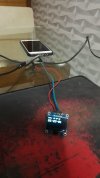
B4R Question About SSD1306 and ESP8266 screen

Cesar_Morisco

Active Member
hello people
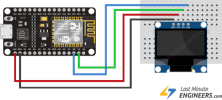
In terms of connecting the SSD1306 display to the esp8266 it doesn't work I use pin D1 and D2 It doesn't work here the example I'm using could someone help about the output pins to use.
I thank
SSD1306:
Sub Process_Globals
    Public Serial1 As Serial
    Public WiFi As ESP8266WiFi
    Public Udp As WiFiUDP
    Public WifiSSID As String="xxx"
    Public WifiPass As String="xxx"
    Private ssd As AdafruitSSD1306
    Private d1pins As D1Pins
    
    
End Sub

Private Sub AppStart
    Serial1.Initialize(115200)
    Log("AppStart")
    ssd.InitializeI2C(d1pins.D6, 0x3c)
    
    ssd.ClearDisplay
    ssd.GFX.SetCursor(0, 0)
    ssd.GFX.ConfigureText(2, ssd.WHITE, False)
    ssd.GFX.DrawText("Wifi ...").DrawText(CRLF).DrawText(CRLF)
    ssd.Display
  
    If WiFi.IsConnected=False Then
        ConnectToNetwork
    End If
    
    'Udp.Initialize(8888,"UDP_PacketArrived")
    ssd.ClearDisplay
    ssd.GFX.SetCursor(0, 0)
    ssd.GFX.ConfigureText(2, ssd.WHITE, False)
    ssd.GFX.DrawText("Wifi .. OK").DrawText(CRLF).DrawText(CRLF)
    ssd.GFX.DrawText("No UDP Data")
    ssd.Display
End Sub

Sub ConnectToNetwork
    If WiFi.IsConnected Then
        Return
    End If
    If WiFi.Connect2(WifiSSID, WifiPass) Then
        Log("Connected successfully to: ", WifiSSID)
        Log(WiFi.LocalIp)
    Else
        Log("Failed to connect.")
    End If
End Sub
 

Mark Read

Well-Known Member
Licensed User
Longtime User
You could try an I2C Scanner. Here is one for the Arduino IDE.

What ESP are you using?

B4X:
/*********
  Rui Santos
  Complete project details at https://randomnerdtutorials.com 
*********/

#include <Wire.h>
 
void setup() {
  Wire.begin();
  Serial.begin(9600);
  Serial.println("\nI2C Scanner");
}
 
void loop() {
  byte error, address;
  int nDevices;
  Serial.println("Scanning...");
  nDevices = 0;
  for(address = 1; address < 127; address++ ) {
    Wire.beginTransmission(address);
    error = Wire.endTransmission();
    if (error == 0) {
      Serial.print("I2C device found at address 0x");
      if (address<16) {
        Serial.print("0");
      }
      Serial.println(address,HEX);
      nDevices++;
    }
    else if (error==4) {
      Serial.print("Unknow error at address 0x");
      if (address<16) {
        Serial.print("0");
      }
      Serial.println(address,HEX);
    }   
  }
  if (nDevices == 0) {
    Serial.println("No I2C devices found\n");
  }
  else {
    Serial.println("done\n");
  }
  delay(5000);         
}
 

Attachments

  • IC2-scanner.txt
    956 bytes · Views: 170
Upvote 0

teddybear

Well-Known Member
Licensed User
You could try an I2C Scanner. Here is one for the Arduino IDE.

What ESP are you using?

B4X:
/*********
  Rui Santos
  Complete project details at https://randomnerdtutorials.com
*********/

#include <Wire.h>
 
void setup() {
  Wire.begin();
  Serial.begin(9600);
  Serial.println("\nI2C Scanner");
}
 
void loop() {
  byte error, address;
  int nDevices;
  Serial.println("Scanning...");
  nDevices = 0;
  for(address = 1; address < 127; address++ ) {
    Wire.beginTransmission(address);
    error = Wire.endTransmission();
    if (error == 0) {
      Serial.print("I2C device found at address 0x");
      if (address<16) {
        Serial.print("0");
      }
      Serial.println(address,HEX);
      nDevices++;
    }
    else if (error==4) {
      Serial.print("Unknow error at address 0x");
      if (address<16) {
        Serial.print("0");
      }
      Serial.println(address,HEX);
    } 
  }
  if (nDevices == 0) {
    Serial.println("No I2C devices found\n");
  }
  else {
    Serial.println("done\n");
  }
  delay(5000);       
}
Here is a b4r snippet for i2c address scanner , The esp is 8266. what is the electric circuit diagram?
 
Upvote 0

Mark Read

Well-Known Member
Licensed User
Longtime User
You are using i2c of esp8266 nodeMCU D1 scl and D2 sda....
but in your code in initialization you use pin D6...is that correct?
it should be
B4X:
ssd.InitializeI2C(d1pins.D1, 0x3c)
As far as i know, his code is correct if Pin D6 is free. Here is my setup.

1688725983629.png
 
Upvote 0

teddybear

Well-Known Member
Licensed User
Upvote 0

candide

Active Member
Licensed User
if you are using wemos D1 mini,
D1 is GPI05 => pin = 5 for your init
D2 is GPIO4 => pin = 4 for your init
by default SCL is pin 5 and SDA is pin 4 (GPIO is the pin corresponding at arduino)

1688743416898.png
 
Upvote 0

Cesar_Morisco

Active Member
Yes I am using NodeMCU ESP8266
D1 and D2
Look at the photo and the same configuration that I am using here
 

Attachments

  • Fritzing-Wiring-OLED-Display-with-ESP8266-NodeMCU.png
    Fritzing-Wiring-OLED-Display-with-ESP8266-NodeMCU.png
    19.1 KB · Views: 153
Upvote 0

candide

Active Member
Licensed User
first step is to check if slave I2C is seen with I2C-scanner provided above :
- what is result of this script ?
 
Upvote 0

Cesar_Morisco

Active Member
hello all
Here for me everything goes wrong kkkk
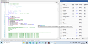
I've done as friends said and it doesn't work for me here the settings I'm using
If anyone has any more advice, I'd appreciate it.
 

Attachments

  • SSD1306.png
    SSD1306.png
    117.2 KB · Views: 142
Upvote 0

teddybear

Well-Known Member
Licensed User
hello all
Here for me everything goes wrong kkkk
I've done as friends said and it doesn't work for me here the settings I'm using
If anyone has any more advice, I'd appreciate it.
1.You'd better post the project, File ->Export As Zip
2.Show us your electric circuit picture as below


微信图片_20230708235934.jpg
 
Upvote 0

Mark Read

Well-Known Member
Licensed User
Longtime User
There is only one thing I can think of. In the directory for rAdafruitSSD1306, there is a file called Adafruit_SSD1306.h. If you open the file with a good text editor (Notepad++ for example) and scroll to line 73. You can see that you have to set the resolution of the display. Have you done/tried this?
Lines 55 to 76 from Adafruit_SSD1306.h:
#define SSD1306_I2C_ADDRESS   0x3C  // 011110+SA0+RW - 0x3C or 0x3D
// Address for 128x32 is 0x3C
// Address for 128x64 is 0x3D (default) or 0x3C (if SA0 is grounded)

/*=========================================================================
    SSD1306 Displays
    -----------------------------------------------------------------------
    The driver is used in multiple displays (128x64, 128x32, etc.).
    Select the appropriate display below to create an appropriately
    sized framebuffer, etc.

    SSD1306_128_64  128x64 pixel display

    SSD1306_128_32  128x32 pixel display

    SSD1306_96_16

    -----------------------------------------------------------------------*/
   #define SSD1306_128_64 <-- comment or uncomment as required! This works for the 0.96" OLED.
//   #define SSD1306_128_32
//   #define SSD1306_96_16
/*=========================================================================*/

As I said before, your code looks correct. Have you a second OLED to try?
 
Upvote 0

Mark Read

Well-Known Member
Licensed User
Longtime User
Just an after thought, what Arduino IDE version are you using?
 
Upvote 0

Cesar_Morisco

Active Member
Hello everything is fine
SSD1306:
#define SSD1306_I2C_ADDRESS   0x3C  // 011110+SA0+RW - 0x3C or 0x3D
// Address for 128x32 is 0x3C
// Address for 128x64 is 0x3D (default) or 0x3C (if SA0 is grounded)

/*=========================================================================
    SSD1306 Displays
    -----------------------------------------------------------------------
    The driver is used in multiple displays (128x64, 128x32, etc.).
    Select the appropriate display below to create an appropriately
    sized framebuffer, etc.

    SSD1306_128_64  128x64 pixel display

    SSD1306_128_32  128x32 pixel display

    SSD1306_96_16

    -----------------------------------------------------------------------*/
//   #define SSD1306_128_64
   #define SSD1306_128_32
//   #define SSD1306_96_16
/*=========================================================================*/
SSD1306:

I made the same clock file and the one you are using does not work


Sub Process_Globals

Public Serial1 As Serial

Private wifi As ESP8266WiFi

Private clock As Timer

Private ssd As AdafruitSSD1306

Private d1pins As D1Pins

End Sub


Private Sub AppStart

Serial1.Initialize(115200)

Log("AppStart")

'example of connecting to a local network

If wifi.Connect2("Help-Info Central Tec 2.4G", "Pp1c2s3m4") Then

Log("Connected to network")

TimeNIST.Start

clock.Initialize("clock_Tick", 1000)

ssd.InitializeI2C(d1pins.D1, 0x3c)

ssd.ClearDisplay

TimeIsAvailable

Else

Log("Failed to connect to network")

End If

End Sub


Public Sub TimeIsAvailable

clock.Enabled = True

End Sub


Private Sub Clock_Tick

ssd.ClearDisplay

ssd.GFX.SetCursor(0, 0)

ssd.GFX.ConfigureText(1, ssd.WHITE, False)

ssd.GFX.DrawText("Date: ").DrawText(TimeNIST.GetDate).DrawText(CRLF).DrawText(CRLF)

ssd.GFX.ConfigureText(2, ssd.WHITE, False)

ssd.GFX.DrawText(NumberFormat(TimeNIST.GetHours, 2, 0)).DrawText(":").DrawText(NumberFormat(TimeNIST.GetMinutes, 2, 0))

ssd.GFX.DrawText(":").DrawText(NumberFormat(TimeNIST.GetSeconds, 2, 0))

ssd.Display

End Sub[/CODE]
 

Attachments

  • Backup SSD1306_Teste 2023-07-09 11.52.zip
    989 bytes · Views: 163
Upvote 0

Mark Read

Well-Known Member
Licensed User
Longtime User
Its good news when everything works. Please use </>CODE tags when posting.

What did you do to get it working? The only thing I can see is the initialise with Pin1.
 
Upvote 0

Cesar_Morisco

Active Member
I want to thank everyone

Now it worked
Here is the code I used As I said I've been using this amazing tool for a few days. I have a lot to learn from you guys thank you so much dear
SSD1306:
Sub Process_Globals
    Public Serial1 As Serial
    Private wifi As ESP8266WiFi
    Private clock As Timer
    Private ssd As AdafruitSSD1306
    Private d1pins As D1Pins
    Private WifiSSID As String=" "
    Private WifiPass As String=" "
End Sub

Private Sub AppStart
    Serial1.Initialize(115200)
    Log("AppStart")
    'example of connecting to a local network
    ssd.InitializeI2C(d1pins.D6, 0x3c)            'initialise SSD1306
    ssd.ClearDisplay
    ssd.GFX.SetCursor(0, 0)
    ssd.GFX.ConfigureText(2, ssd.WHITE, False)
    ssd.GFX.DrawText("Wifi ...").DrawText(CRLF).DrawText(CRLF)
    ssd.Display
    If wifi.IsConnected=False Then
        ConnectToNetwork
    End If
  
End Sub

Sub ConnectToNetwork
    If wifi.IsConnected Then
        Return
    End If
    If wifi.Connect2(WifiSSID, WifiPass) Then
        Log("Connected successfully to: ", WifiSSID)
        Log(wifi.LocalIp)
        ssd.ClearDisplay
        ssd.GFX.SetCursor(0, 0)
        ssd.GFX.ConfigureText(2, ssd.WHITE, False)
        ssd.GFX.DrawText("Wifi .. OK").DrawText(CRLF).DrawText(CRLF)
        ssd.GFX.DrawText("IP:")
        ssd.GFX.DrawText(wifi.LocalIp).DrawText(CRLF).DrawText(CRLF)
        ssd.Display
      
        TimeNIST.Start
        clock.Initialize("clock_Tick", 1000)
        TimeIsAvailable
      
    Else
        Log("Failed to connect.")
    End If
End Sub

Public Sub TimeIsAvailable
    clock.Enabled = True
End Sub

Private Sub Clock_Tick
    ssd.ClearDisplay
    ssd.GFX.SetCursor(0, 0)
    ssd.GFX.ConfigureText(1, ssd.WHITE, False)
    ssd.GFX.DrawText("Date: ").DrawText(TimeNIST.GetDate).DrawText(CRLF).DrawText(CRLF)
    ssd.GFX.ConfigureText(2, ssd.WHITE, False)
    ssd.GFX.DrawText(NumberFormat(TimeNIST.GetHours, 2, 0)).DrawText(":").DrawText(NumberFormat(TimeNIST.GetMinutes, 2, 0))
    ssd.GFX.DrawText(":").DrawText(NumberFormat(TimeNIST.GetSeconds, 2, 0))
    ssd.Display
End Sub
 

Attachments

  • 20230709_191313.jpg
    20230709_191313.jpg
    41.4 KB · Views: 140
Upvote 0
Top