B4R Library rAdafruitSSD1306 - OLED displays

This is a wrapper for this open source project: https://github.com/adafruit/Adafruit_SSD1306

It depends on rAdafruitGFX library: https://www.b4x.com/android/forum/threads/radafruitgfx.68904/

It allows drawing graphics and text on supported monochrome OLED modules.

I've tested it with an I2C module. You need to pass the I2C address (default is 0x3c) and an available pin (4) in the example.

The GFX field from the SSD object is used for the drawings.
B4X:
ssd.GFX.DrawCircle(px, py, radius, ssd.BLACK, True)
The drawings will only appear on the module after you call ssd.Display.

There are two examples attached.
The first is a bouncing ball:


The second one, which runs on ESP8266, implements a clock:
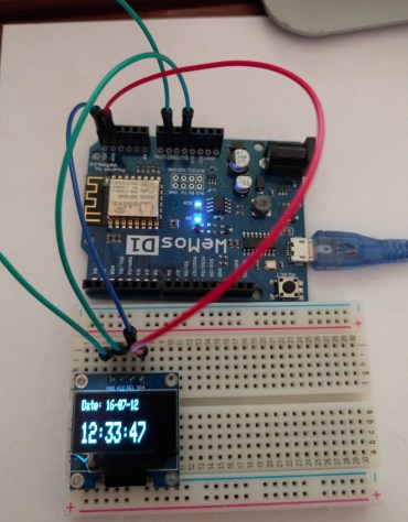
SS-2016-07-12_15.41.19.jpg
 

Attachments

  • BouncingBall.zip
    851 bytes · Views: 1,057
  • Clock.zip
    1.8 KB · Views: 1,206
  • rAdafruitSSD1306.zip
    33.4 KB · Views: 1,131
Last edited:

Mostez

Well-Known Member
Licensed User
Longtime User
Hi Erel,
Would you please give short example how to initialize OLED in SPI mode, specially I don't have CS pin on OLED module

Thanks
 

Mostez

Well-Known Member
Licensed User
Longtime User
Hi,
following your example, I tried to compile code listed, but I got this error message:

B4X:
#AutoFlushLogs: True
#CheckArrayBounds: True
'set the stack buffer size!
#StackBufferSize: 600

Sub Process_Globals
    Private ssd As AdafruitSSD1305
    Private resPIN As Pin
    Private dcPIN As Pin
    Private csPIN As Pin
End Sub

Private Sub AppStart
    csPIN.Initialize(5, csPIN.MODE_INPUT)
    resPIN.Initialize(6, resPIN.MODE_INPUT)
    dcPIN.Initialize(7, dcPIN.MODE_INPUT)
   
   
    ssd.InitializeHSPI(dcPIN.PinNumber,resPIN.PinNumber,csPIN.PinNumber )
    ssd.ClearDisplay   
    ssd.GFX.SetCursor(0, 0)
    ssd.GFX.ConfigureText(1, ssd.WHITE, False)
    ssd.GFX.DrawText("Hello World")
    ssd.Display
   
End Sub

B4R version: 1.20
Parsing code. (0.00s)
Compiling code. (0.01s)
Building project (0.02s)
Compiling & deploying Ino project (Arduino Leonardo - COM26) Error

Adafruit_SSD1306.cpp:33:18: fatal error: Wire.h: No such file or directory
#include <Wire.h>
^
compilation terminated.
Error compiling.
 

Mostez

Well-Known Member
Licensed User
Longtime User
upgraded Java VM and re-installed Arduino IDE, no compiling errors, changed appstart, but still have blank OLED :(

B4X:
Private Sub AppStart
    csPIN.Initialize(5, csPIN.MODE_OUTPUT)
    resPIN.Initialize(6, resPIN.MODE_OUTPUT)
    dcPIN.Initialize(7, dcPIN.MODE_OUTPUT)
  
  
    ssd.InitializeHSPI(dcPIN.PinNumber,resPIN.PinNumber,csPIN.PinNumber )
    ssd.ClearDisplay  
    ssd.GFX.SetCursor(0, 0)
    ssd.GFX.ConfigureText(1, ssd.WHITE, False)
    ssd.GFX.DrawText("Hello World")
    ssd.Display
 
End Sub
 

Mostez

Well-Known Member
Licensed User
Longtime User
I tried this example and worked OK, i made connection as follows:

#define OLED_MOSI 0 'connected to OLED SDA
#define OLED_CLK 1 'connected to OLED SCL
#define OLED_DC 2 'connected to OLED DC
#define OLED_CS 3 'not connected, dont have CS pin
#define OLED_RESET 4 'connected to OLED RST
 

Mostez

Well-Known Member
Licensed User
Longtime User
well, I made some changes to OLED board to change board intrface to IIC, according to this article, it worked very well with bouncing ball example and I wrote 'hello world'. but unfortunately, it worked only when uploading B4R for first time, when re-power Arduino i get blank screen. ps OLED DC pin is connectedto GND
 

Mostez

Well-Known Member
Licensed User
Longtime User
No, it works only when I upload the code from B4R, if I disconnect USB cable and re-connect it again, it does not work.
 

Mostez

Well-Known Member
Licensed User
Longtime User
got it :)
RES pin is connected to internally pull-up pin i.e. pin 7, this pin should be initialized in pull-up mode before calling OLED initialize statement. I think it could be possible also to connect RES pin to hard wired 10K pull-up resistor then no need to add pin initialization line.

B4X:
rs.Initialize(7,rs.MODE_INPUT_PULLUP)
ssd.InitializeI2C(7, 0x3c)
 

jarda

Member
Licensed User
Longtime User
Hi,
following your example, I tried to compile code listed, but I got this error message:

In file included from sketch\B4RDefines.h:27:0,
from sketch\AsyncStreams.cpp:1:
rAdafruitSSD1306.h:11: error: 'B4RAdafruitGFX' does not name a type
B4RAdafruitGFX gfx;
^
rAdafruitSSD1306.h:15: error: 'B4RAdafruitGFX' does not name a type
B4RAdafruitGFX* GFX;
^
exit status 1
'B4RAdafruitGFX' does not name a type
 

Attachments

  • Untitled-3.jpg
    Untitled-3.jpg
    246.9 KB · Views: 725

jarda

Member
Licensed User
Longtime User
Hi

New Install and compile Ok..

I have this problem.

My HW (ESP Wroom) has otherwise SCL on IO14 and SDA on IO2 pins (not 4, 5) I2C mode.

Can it change?

Jarek
 
Last edited:

jarda

Member
Licensed User
Longtime User
Hi

sorry. it's not true...


....

appl from : http://playground.arduino.cc/Main/I2cScanner


for(address = 1; address < 127; address++ )

returned

Scanning...
No I2C devices found

Scanning...
No I2C devices found

Scanning...
No I2C devices found

Scanning...
No I2C devices found

Scanning...
No I2C devices found
...........


In Adafruit_SSD1306.CPP is

/*********************************************************************
This is a library for our Monochrome OLEDs based on SSD1306 drivers

Pick one up today in the adafruit shop!
------> http://www.adafruit.com/category/63_98

These displays use SPI to communicate, 4 or 5 pins are required to
interface

Adafruit invests time and resources providing this open source code,
please support Adafruit and open-source hardware by purchasing
products from Adafruit!

Written by Limor Fried/Ladyada for Adafruit Industries.
BSD license, check license.txt for more information
All text above, and the splash screen below must be included in any redistribution


Jarek
 
Last edited:

monki

Active Member
Licensed User
Longtime User
Hello,
in the arduino libary there are the functions start scroll left, right, etc
how can I use in B4R?

monki
 
Top