hello people
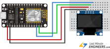
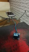
In terms of connecting the SSD1306 display to the esp8266 it doesn't work I use pin D1 and D2 It doesn't work here the example I'm using could someone help about the output pins to use.
I thank
In terms of connecting the SSD1306 display to the esp8266 it doesn't work I use pin D1 and D2 It doesn't work here the example I'm using could someone help about the output pins to use.
I thank
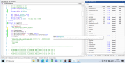
SSD1306:
Sub Process_Globals
    Public Serial1 As Serial
    Public WiFi As ESP8266WiFi
    Public Udp As WiFiUDP
    Public WifiSSID As String="xxx"
    Public WifiPass As String="xxx"
    Private ssd As AdafruitSSD1306
    Private d1pins As D1Pins


End Sub

Private Sub AppStart
    Serial1.Initialize(115200)
    Log("AppStart")
    ssd.InitializeI2C(d1pins.D6, 0x3c)

    ssd.ClearDisplay
    ssd.GFX.SetCursor(0, 0)
    ssd.GFX.ConfigureText(2, ssd.WHITE, False)
    ssd.GFX.DrawText("Wifi ...").DrawText(CRLF).DrawText(CRLF)
    ssd.Display

    If WiFi.IsConnected=False Then
        ConnectToNetwork
    End If

    'Udp.Initialize(8888,"UDP_PacketArrived")
    ssd.ClearDisplay
    ssd.GFX.SetCursor(0, 0)
    ssd.GFX.ConfigureText(2, ssd.WHITE, False)
    ssd.GFX.DrawText("Wifi .. OK").DrawText(CRLF).DrawText(CRLF)
    ssd.GFX.DrawText("No UDP Data")
    ssd.Display
End Sub

Sub ConnectToNetwork
    If WiFi.IsConnected Then
        Return
    End If
    If WiFi.Connect2(WifiSSID, WifiPass) Then
        Log("Connected successfully to: ", WifiSSID)
        Log(WiFi.LocalIp)
    Else
        Log("Failed to connect.")
    End If
End Sub