B4R Question Build a smart switch with ESP8266

aeric

Expert
Licensed User
Longtime User
I learn that there are some WiFi smart switches in the market like Shelly, Tuya and Sonoff. It is build in with ESP8266 and relay in a small form factor.

What if I want to build something similar?

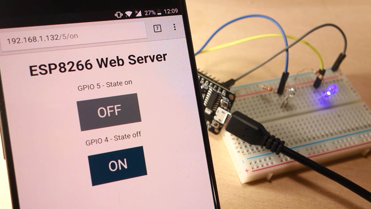
I can say all of the projects on the Internet show that the ESP is powered by USB.

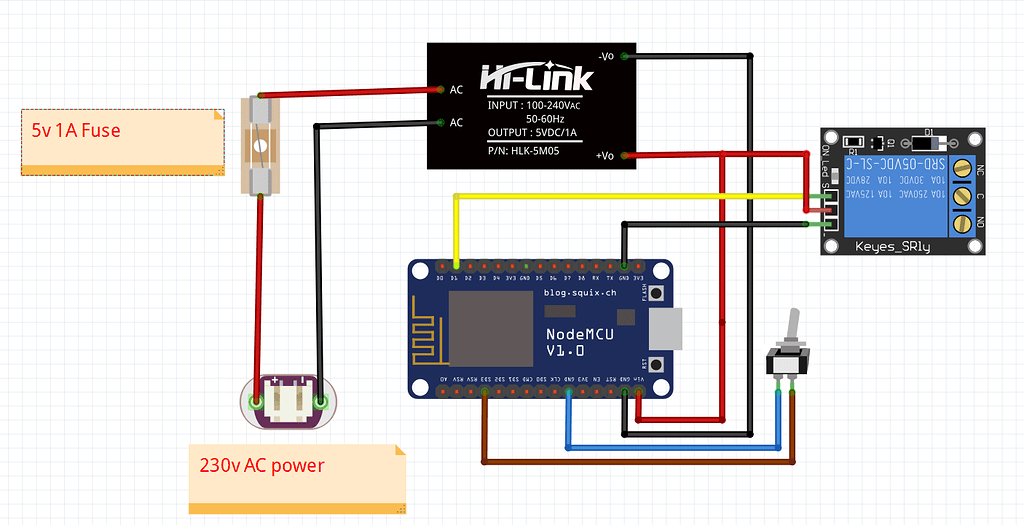
My question is why not use a 220v AC to 3.3v/5v DC converter that get the power from Main electric source so I don't need to get messy with another charger?

 
Last edited:

derez

Expert
Licensed User
Longtime User
A connection scheme I hope everyone can understand:
Use a 5v power supply with an adaptor , use 2 jumper wires to connect Vcc to Vin in the esp8266 and GRD to G there.
The relay in the picture is 3v so connect the 3.3v supply to the relay's Vcc and the ground to GRN. Connect any digital pin that will control the relay, in the picture I used D7.
The wiring to the AC device, in the picture a bulb : it has two wires (not counting the earth, usualy green or yellow), leave one wire connected and cut the other and make an extension through the relay AC side. Use the NO pin and the COM to connect to the split wire of the lamp. The NO (normally open) pin will connect with the com when the control pin D7 is true.
Before you connect to AC power - isolate the connections to COM and NO so you will not touch it by mistake !!!
Connect to AC power for a short time when control is on and take the AC plug out, then check the relay's temperature. If it is hot - the power that goes through the relay is too large and you need a higher level relay (larger current).

If you use a 5v relay you need a logic converter to make the control signal from D7 a 5v instead of 3.3v.
 

Attachments

  • conn.png
    conn.png
    274.4 KB · Views: 55
Last edited:
Upvote 0

pappicio

Active Member
Licensed User
Longtime User
A connection scheme I hope everyone can understand:
Use a 5v power supply with an adaptor , use 2 jumper wires to connect Vcc to Vin in the esp8266 and GRD to G there.
The relay in the picture is 3v so connect the 3.3v supply to the relay's Vcc and the ground to GRN. Connect any digital pin that will control the relay, in the picture I used D7.
The wiring to the AC device, in the picture a bulb : it has two wires (not counting the earth, usualy green or yellow), leave one wire connected and cut the other and make an extension through the relay AC side. Use the NO pin and the COM to connect to the split wire of the lamp. The NO (normally open) pin will connect with the com when the control pin D7 is true.
Before you connect to AC power - isolate the connections to COM and NO so you will not touch it by mistake !!!
Connect to AC power for a short time when control is on and take the AC plug out, then check the relay's temperature. If it is hot - the power that goes through the relay is too large and you need a higher level relay (larger current).

If you use a 5v relay you need a logic converter to make the control signal from D7 a 5v instead of 3.3v.
for 5V Relay, only need to wire VCC of relay module to Vin of ESP8266, that source is 5V, while IN pin of relay is OK on 3.3V esp8266 pin (the relay modules have a transistor, so also 3V can be used to POWER they ON).
 
Last edited:
Upvote 0

RJB

Active Member
Licensed User
Longtime User
It's clear from all of the above that people are willing to risk their lives to experiment with mains voltages.
Please, if you are not qualified yourself:
If you are doing something for your own use then get advise from someone who understands these things. You may kill yourself otherwise.
If you are doing something for other people or to sell then get advise from someone who understands these things. You may kill other people otherwise.

I'm sure most countries have rules or laws to cover this. In the UK you can be sent to prison if you break them. Presumably you could also face a charge of manslaughter if someone dies.
 
Upvote 0

KiloBravo

Active Member
Licensed User
IMHO, Connecting to the mains I would use a USB charger as mentioned above.

Depending on your "load" I would use MOC3021 or similar. Plenty of diagrams on the net.
I have used a MOC3011 for turning lights on and off. 120v mains. Should have used the zero crossing version.
https://www.digchip.com/datasheets/parts/datasheet/161/MOC3011.php (MOC3031?)

Also Art of Electronics by Horowitz and Hill is one of my favorite Electronic Books.
Any Edition if you can find one. I think they are out with the 3rd Edition now.

Of course you can just ask ChatGPT now. :)

My stuff is all hobby work not for sale or for a product.
 
Upvote 0

aeric

Expert
Licensed User
Longtime User
I successfully make the 5v single relay and esp8266 work and control using a web page. I am using Arduino WebServer code instead of B4R MQTT.

After I continuous on and off, like 3 to 4 cycles, it seems the relay stop working. I just hear the click sound and red led turn on at the relay but the output does not turn off anymore.

I am using USB phone charger 5V 1A to power the ESP8266. No AC to DC converter is used.
 
Upvote 0

aeric

Expert
Licensed User
Longtime User
I remembered 1 post on the web. Knock it!

I tried, it works!!!

So the switch in the relay is stucked.

I make a conclusion that this 50 cents relay is not reliable.

Maybe one will consider to go for a solid state relay if he get more serious.

Edit: One reason which I think is likely to happen is the white LED lights that I am using for the experiment has a magnetic base so it may cause the relay to attracted to the magnet. Unfortunately I don't have other electric appliance at home to test.

Edit: Second reason I can think of is the relay was bought and keep sitting in my box for quite a while so it may not as good as a new one.
 
Last edited:
Upvote 0

aeric

Expert
Licensed User
Longtime User
Connection to the 5V relay

Link to ESP8266 Web Server
 
Upvote 0
Top