B4R Question Choosing the correct Power Supply?

ilan

Expert
Licensed User
Longtime User
hi

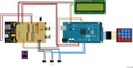
i am working on a project that includes 3 stepper motors with an L298n driver for each motor.

i am connecting all motors to a external power supply 12v - 3A.
what i get is that if i move 1 stepper motor it works fine if i try to move another one arduino is shutting down and again on.
and again if i move another stepper motor it works fine as long as i try to move the second motor it shuts down and again on (light gets dim and again normal) so my first thinking was
there is not enough current flowing so i wanted to order a 12v - 5A power supply but i have another power supply where i can set the voltage

this one:


it is a 3-24v with 3A power supply.

so i tried to set a lower voltage and to my surprise if i set between 6-7 volt i can move all 3 stepper motors if i set lower then 6 or higher then 7 again it shuts down if i try to move more then 1 stepper motor.

why is it like that? is it the arudino that shuts down the motors because the high amperage?
i know that the motors can run with 12 volts and the l298 also so i don't think it is the voltage that makes the problem i think the 3A is to high. am i right?
should i try a 12v with 2A?

this is the stepper motor i use:


and this is the l298n driver:


thanx
 
Last edited:

ilan

Expert
Licensed User
Longtime User
ok thanx guys for your feed back i will look for another power supply 5-6A and see if it is better.

what is the simplest way to measure the current (amps) that coming out from a power supply?
can i connect a multimeter directly to measure the current like i can measure the voltage? or should i use a resistor between the multimeter and the power supply.

i know that if i want to measure the current the multimeter needs to be connected in serial within the circuit not like measuring the voltage and also i need to put the pin of the multimeter to 10A port. i would like to know how much current the powersupply is giving.

thanx
 
Upvote 0

RJB

Active Member
Licensed User
Longtime User
The meter should be connected as you say, in series and through the 10A input. Be aware though that it will drop a voltage across it. It should be small but at the currents you are measuring might be noticeable. If you have another meter you could measure the voltage actually getting to the motor just to be sure.
 
Upvote 0

Sifu

Active Member
Do NOT connect a Ampere meter directly between + and - from your supply. It will create a short, blowing up the fuse in your meter.
Next to that IF your supply can not handle a short between + and - you'll destroy that too. If it can handle a short it will go in hiccup mode.

You need to use a variable resistor which can handle the current at the delivered voltage so U/I=R. Then slowly decrease the resistance and the current will increase. Also monitor the voltage until the point that it will drop, then you know the max current. Note that due to increase of heat, the output voltage/current can drop too if you go over the normal limit as written on the ratings label. Normally you would use a power analyzer to do such measurement.

A smaller stepper motor like NEMA 40 size can do something like 1.3A when constantly powered while stepping or locking. How much is each motor rated?
 
Upvote 0

RJB

Active Member
Licensed User
Longtime User
Note that the motors listed in #1 have a 'rated current' of 1.7A.
A 12v supply is being used.
If it does draw 1.7A that's a peak of 20.4 watts for one motor, quite a big (and no doubt expensive) variable resistor.
I think the power supply currently (!) being used is 3A so to test it's limiting will need a 36W+ resister.
From what's been said it seems pretty certain the motor load is exceeding the PSU capability so the higher power PSU is a good option to try.
For comparison one of my 3D printers came with a 8amp PSU. I know there is also the heater involved (only the hot end as it doesn't have a heated bed) but the 3 motors take a fair bit of that.
 
Upvote 0

Mark Read

Well-Known Member
Licensed User
Longtime User
HI ilan, in your post #7, you have connected the controllers in parallel. Each motor has a constant resisitance based on the windings of the motor. This means the current required for all three is simply added i.e. 5.1A. What you don't mention is the voltage rating of the motors or the resistance of the coils. This would give you an optimal voltage to use. For example, I have 2 Nema 17 motors with 1A, 5ohm = 5 V. Both of them run quite nicely on a 7.5V, 2.5A supply, including the Arduino. Why have I increased the voltage and have not used a 5V supply? The L298 has an internal voltage drop of 1.2V roughly. You only see this if you look at the data sheet for the chip itself, not the breakout board.
So I would suggest 150% of your motor voltage rating and aroung 6A should be enough. The attached pdf might also be of use for you.
 

Attachments

  • L298N Motor Driver.pdf
    470.2 KB · Views: 116
Last edited:
Upvote 0

ilan

Expert
Licensed User
Longtime User
HI ilan, in your post #7, you have connected the controllers in parallel. Each motor has a constant resisitance based on the windings of the motor. This means the current required for all three is simply added i.e. 5.1A. What you don't mention is the voltage rating of the motors or the resistance of the coils. This would give you an optimal voltage to use. For example, I have 2 Nema 17 motors with 1A, 5ohm = 5 V. Both of them run quite nicely on a 7.5V, 2.5A supply, including the Arduino. Why have I increased the voltage and have not used a 5V supply? The L298 has an internal voltage drop of 1.2V roughly. You only see this if you look at the data sheet for the chip itself, not the breakout board.
So I would suggest 150% of your motor voltage rating and aroung 6A should be enough. The attached pdf might also be of use for you.
Thanx a lot, i will have a look at the pdf when i get home. So basically everybody is suggesting more power 💪

i tried 5v with 6amps but nothing happens so i will beed to find a 12v with 6amps.

what are u guys using as power supply for your project? Is there something where i can set the voltage and amperes? Instead of everytime buy a seprat SPU i would like to buy one where i can set the amps and voltage. Any suggestions?
 
Upvote 0

Mark Read

Well-Known Member
Licensed User
Longtime User
For testing you could use a so called laboratory power supply. These have mostly 2 modes: constant voltage or constant current. They work up to 24V with 20A. Recken with about €70.

 
Upvote 0

ilan

Expert
Licensed User
Longtime User
Ok so i have a short update. I managed to get a regulated power supply that can give 0-36v and 0-12A

so i set a limit of 6A and set the PSU to 12V and i managed to drive all 3 Stepper motors. they also sounds much better now. before when they where stopping and holding the position they made weird sounds and vibration now they look like they work fine.

but what i noticed is that the voltage is dropping to around 6v and if i measured the l298n 12v input pin and the ground i got 5.6v on each driver the same.
is that normal?

i was thinking maybe i should give more volts and remove the 12v jumper from the drivers but it says that the pax power is 20Watt so giving more volt with 6A will be to much i guess.

should i order a 12v with 6A PSU and leave it like this? it did work fine on the voltage dropped.

thanx
 
Last edited:
Upvote 0

ilan

Expert
Licensed User
Longtime User
2.jpg


what means the marked lines? i guess when the motors are working it is driving on 4.5-5.5V ? because this is what i get.

HI ilan, in your post #7, you have connected the controllers in parallel. Each motor has a constant resisitance based on the windings of the motor. This means the current required for all three is simply added i.e. 5.1A. What you don't mention is the voltage rating of the motors or the resistance of the coils. This would give you an optimal voltage to use. For example, I have 2 Nema 17 motors with 1A, 5ohm = 5 V. Both of them run quite nicely on a 7.5V, 2.5A supply, including the Arduino. Why have I increased the voltage and have not used a 5V supply? The L298 has an internal voltage drop of 1.2V roughly. You only see this if you look at the data sheet for the chip itself, not the breakout board.
So I would suggest 150% of your motor voltage rating and aroung 6A should be enough. The attached pdf might also be of use for you.

thankx for the PDF but in the PDF the 12v and 5v are opposite then on the seller description. could it be a mistake on the PDF or the seller page?

thanx
 
Upvote 0

Mark Read

Well-Known Member
Licensed User
Longtime User
thankx for the PDF but in the PDF the 12v and 5v are opposite then on the seller description. could it be a mistake on the PDF or the seller page?

This is only the difference between suppliers and how they make the boards. Use the connection as marked on your board.


The two lines you have marked are regarding the control signal from the Arduino:

If you use 12V (Jumper J8 is set!!!), then the 5V is an output for the Arduino. Otherwise the 5V is an input from the Arduino and the jumper j8 must NOT be set. The Arduino delivers 5V which fits the range of 4.5V - 5.5V as marked in your post.

The connections IN1-IN4 are the digital control pins to/from the Arduino and the voltage should also be in the correct range. Real Arduino's give exactly the required voltage. Clones maybe not but still within the range specified.


I would suggest either:
You keep the 12V supply and increase the current SLOWLY and see if the motors run better.

OR

You measure the resistance over the coil and find the minimum voltage required (Voltage = Current (in your case 1.7A) x Resistance). Check your power requirement is not above 20W (P=IxIxR). Set your voltage to 150% of this and set the current to 5.1A and increase the current slowly.


As an afterthought, to power these very strong motors, the L298 is not the best choice as there is no current limiting. A better choice would be an A4988 or DVR8825 board which have current control, need less wiring and support micro-stepping.
 
Last edited:
Upvote 0

ilan

Expert
Licensed User
Longtime User
Thank you very much for your detailed answer. I actually also bought 3 dvr8825 but there is no tutorial for it using b4r so i went with the l298. Do you have maybe an example project how to control the stepper motors using the dvr8825 drivers and how to wire them? Can i use the same stepper motor library using those drivers too?

those are the drivers i also have:

B2EFAA01-E7C2-4217-8AFD-FA97CDE80C13.jpeg
 
Upvote 0

Mark Read

Well-Known Member
Licensed User
Longtime User
I have uploaded a complete example here which shows how to control 2 motors with 2 DVR8825 controllers. There is a lot of code for display and keyboard but take what you need. The wiring is commented in the code. You will need to set the maximum current (very important) but it is easy to do. This will help a lot.

No special libraries are needed in B4R. Here is also a simpler code just to check the motors.

This link should also help.
 

Attachments

  • motor-drv-test.zip
    994 bytes · Views: 108
Last edited:
Upvote 0

Mark Read

Well-Known Member
Licensed User
Longtime User
Just found the fritzing plan which you can check. The DVR8825 is moved off the pcb but the orientation is correct.
 

Attachments

  • dipper_bb.png
    dipper_bb.png
    255.1 KB · Views: 123
Upvote 0

ilan

Expert
Licensed User
Longtime User
I have uploaded a complete example here which shows how to control 2 motors with 2 DVR8825 controllers. There is a lot of code for display and keyboard but take what you need. The wiring is commented in the code. You will need to set the maximum current (very important) but it is easy to do. This will help a lot.

No special libraries are needed in B4R. Here is also a simpler code just to check the motors.

This link should also help.

thank you very much, will check it out 🙏🏻🙏🏻🙏🏻
 
Upvote 0

ilan

Expert
Licensed User
Longtime User
I have uploaded a complete example here which shows how to control 2 motors with 2 DVR8825 controllers. There is a lot of code for display and keyboard but take what you need. The wiring is commented in the code. You will need to set the maximum current (very important) but it is easy to do. This will help a lot.

No special libraries are needed in B4R. Here is also a simpler code just to check the motors.

This link should also help.
Hi mark,

thanx again for your test project. I just tried it now but i am not getting a correct behavior.

the motor is not rotating to one direction it is more shaking and trying to rotate.

here is a video, can u figure out what i have done wrong?

 
Upvote 0

Mark Read

Well-Known Member
Licensed User
Longtime User
Difficult to say but did you set the current (ie. voltage) on the DVR8825 controller? It looks like you have wired the coils wrong. Try changing the motor connections on the DVR. Only try to run for a short time!
 
Upvote 0

ilan

Expert
Licensed User
Longtime User
Difficult to say but did you set the current (ie. voltage) on the DVR8825 controller? It looks like you have wired the coils wrong. Try changing the motor connections on the DVR. Only try to run for a short time!
i have tried to change the current but it did not change anything and also changing the wires did nothing.
maybe i need to set the resolution to lower?
i think that the coils are wired correctly.
 
Upvote 0

Mark Read

Well-Known Member
Licensed User
Longtime User
i think that the coils are wired correctly.
Check them with a multimeter please, don't assume. Low resistance = a coil. High resistance = wrong connection.

Have you also tried changing the plus and minus wires fromeach coil?
 
Upvote 0

ilan

Expert
Licensed User
Longtime User
Check them with a multimeter please, don't assume. Low resistance = a coil. High resistance = wrong connection.

Have you also tried changing the plus and minus wires fromeach coil?
yes i have tried but i am not sure why i get this behavior.
with the l298 i had no issues.

i use a 1000uF capacitor. that should not be the issue right?
 
Upvote 0
Top