Share My Creation control your fan or AC bulb...

Probably not my most complex B4A App :)

But just to show how easy it can be to participate to IoT adventure.

My setup is composed of :
- an ESP8266 board (arduino programmed)
- a power circuit to hash the Main 220V with a triac
- B4A + httpUtils2 lib

Here is the schematics for the power part :
schematics.png


Needless to say that this circuit is connected to MAINS 220V. It can be letal.
Do not try to reproduce it if you are not aware of this danger...


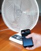
and the result with a fan and a bulb


Attachments

  • fan.jpg
    fan.jpg
    185.5 KB · Views: 3,104
Last edited:

freedom2000

Well-Known Member
Licensed User
Longtime User
Just for fun : THE SOURCE CODE ;)

I do like simplicity and efficiency of httpUtils2 ...

Timer1 is there to avoid blocking the socket communication by too frequent messages...
I don't know if there is a more clever solution ?

B4X:
Sub Globals
    'These global variables will be redeclared each time the activity is created.
    'These variables can only be accessed from this module.
    Dim Sb As SeekBar
    Dim job1 As HttpJob
    Dim Timer1 As Timer
End Sub

Sub Activity_Create(FirstTime As Boolean)
 
   job1.Initialize("Job1", Me)
     Activity.LoadLayout("1")
End Sub

Sub Activity_Resume
Timer1.Initialize("timer1", 100)
End Sub

Sub Activity_Pause (UserClosed As Boolean)
End Sub

Sub JobDone (Job As HttpJob)
   'Log("JobName = " & Job.JobName & ", Success = " & Job.Success)
   If Job.Success = True Then
      Select Job.JobName
         Case "Job1"
            'print the result to the logs
           ' Log(Job.GetString)
      End Select
   Else
      Log("Error: " & Job.ErrorMessage)
      ToastMessageShow("Error: " & Job.ErrorMessage, True)
   End If
   Job.Release
End Sub

Sub Sb_ValueChanged (Value As Int, UserChanged As Boolean)
    'Send a GET request
    Timer1.Enabled = True
End Sub
Sub Timer1_Tick
       job1.Download2("http://192.168.0.23", Array As String("b", 2*Sb.Value))
    Timer1.Enabled = False
End Sub
 

freedom2000

Well-Known Member
Licensed User
Longtime User
Already 3 "likes" in less than one hour :confused:

So here is how it works on the micro controler side.

Stay concentrated as my english is not totally "native" and it's a little technical ...


Basically R1, R2 and D1 feed an optocoupler with AC signal clamped at 0.6V by D1 and the opto LED.
Thus it produces a square signal crossing 0V when the Mains itself is at 0V. This signal is output on the isolated side of the optocoupler and is sent to the ESP8266.

ESP8266 is then computing a delay to switch on the MOC during a very short pulse. Doing this enables the triac to switch on only during a short fraction of the 50Hz (or 60Hz) period. The higher the delay the more the light is dimmed.
 
Last edited:

giga

Well-Known Member
Licensed User
Longtime User
Already 3 "likes" in less than one hour :confused:

So here is how it works on the micro controler side.

GREAT JOB!! Everyone likes to see the power of the microcontroller and B4X products.:):)
 
Top