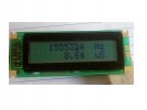
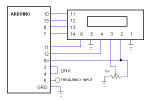
The Arduino generates an accurate 1 second time base for the counter by cascading timer0 and timer2. Part of the B4R code is in C for setting the timers/counters of the Atmega328, this way the accuracy follows the 16 MHz crystal. The link between digital inputs 3 and 4 connects the output of timer2, 250 Hz, to input of timer0. Input of frequency is the input of timer1. Timer1 is a 16 bits timer, when it overflows it advances overF register. At the end of the 1 second the frequency and period are displayed.
Share My Creation Frequency counter
- Thread starter moty22
- Start date
-
- Tags
- frequency counter lcd
- Similar Threads Similar Threads