Well, all of this is theory but I think it should work ") . Also, if a neopixel library for ESP already exists, the only advantage would be that you free resources for the user program since you are giving the control to a hardware resource
. Also, if a neopixel library for ESP already exists, the only advantage would be that you free resources for the user program since you are giving the control to a hardware resource
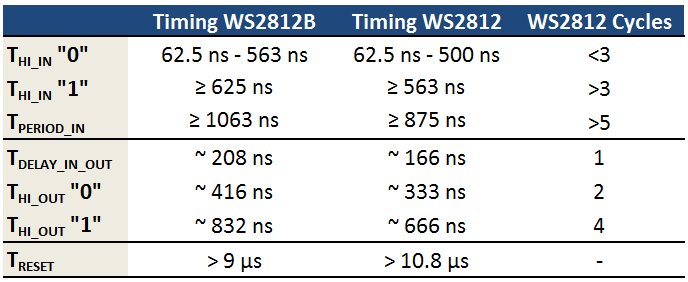
What I mean is that, if for instance, for WS2812 the timings are
symbol "1" --> 660nsec High + 330 nsec low --> 2 basic period HIGH + 1 basic period LOW (let's define a "basic" as a 330nsec period)
symbol "0" --> 330nsec high + 660 nsec low --> 1 basic period HIGH + 2 basic period LOW
Suppose we have N leds. For each one we need 24 bits (as in APA102). The trick is to convert these 24*N "WS2812 bits" to 3*24*N SPI bits
For instance, if the sequence to be sent is
11010011....
We previously prepare the frame buffer converting them to (each 3 bits here will correspond to one original bit)
110 110 100 110 100 100 110 110 ..... ---> grouping them into bytes --> 0xDA 0x69 0x36 ....
Then we set up the HSPI clock to 3MHz we give it the buffer and it automatically sends it. When it finishes we send the following bytes.
As the HSPI in ESP8266 can be, as much, 20bytes, I would limit it to 18 bytes, which would allow us for 2 "complete" leds
18 [bytes]*8 [spi_bits/byte]/3[spi_bits/neopixel_bit])/24 [neopixel_bit/led] --> 2 leds
I am preparing my ESP-Jorduino since I broke my previous one so I can't test it yet. Will do it when ready.

. Also, if a neopixel library for ESP already exists, the only advantage would be that you free resources for the user program since you are giving the control to a hardware resourceWhat I mean is that, if for instance, for WS2812 the timings are
symbol "1" --> 660nsec High + 330 nsec low --> 2 basic period HIGH + 1 basic period LOW (let's define a "basic" as a 330nsec period)
symbol "0" --> 330nsec high + 660 nsec low --> 1 basic period HIGH + 2 basic period LOW
Suppose we have N leds. For each one we need 24 bits (as in APA102). The trick is to convert these 24*N "WS2812 bits" to 3*24*N SPI bits
For instance, if the sequence to be sent is
11010011....
We previously prepare the frame buffer converting them to (each 3 bits here will correspond to one original bit)
110 110 100 110 100 100 110 110 ..... ---> grouping them into bytes --> 0xDA 0x69 0x36 ....
Then we set up the HSPI clock to 3MHz we give it the buffer and it automatically sends it. When it finishes we send the following bytes.
As the HSPI in ESP8266 can be, as much, 20bytes, I would limit it to 18 bytes, which would allow us for 2 "complete" leds
18 [bytes]*8 [spi_bits/byte]/3[spi_bits/neopixel_bit])/24 [neopixel_bit/led] --> 2 leds
I am preparing my ESP-Jorduino
since I broke my previous one so I can't test it yet. Will do it when ready.