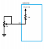
The value of the internal pullup resistor (Rup) is around 20k.
In A0 you will find (voltage divider Rx/Rup):
Vx=Vcc*Rx/(Rx+20k)
So you will never obtain the full-range voltage (0-5 Volts), but less than 5V, depending on the maximum value of the resistance of the potentiometer.
For example, considering the formula, with Rx at its maximum,
- if you have a 1k potentiometer, the range will be 0-0.2V
- if you have a 20k potentiometer, the range will be 0-2.5V
- if you have a 100k potentiometer, the range will be 0-4.16V
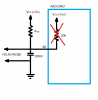
When the knob is versus the ground, you will always find a value close to 0V (it depends on wiring resistance)
Usually the free wire of the potentiometer is connected to the central one: this reduces noise for large resistors and reduces glitches dued to mechanical defects.
Without external power supply, you will never burn your pin, for sure...
Hope this helps