B4R Tutorial ESP8266 + Relay = Let there be light

Relays are electronic switches that allow low power (voltage) devices to control high power circuits.

In this example the ESP8266 board controls a regular 220v light bulb.

*** High power electricity can be dangerous. Handle with care. ***
The relay and the wires must be boxed. Touching any element can be lethal.

(The video was removed, it showed an ESP8266 connected to a light bulb through the relay, and controlled by an Android device.)

Controlling the relay is simple.

SS-2016-10-05_12.19.10.jpg


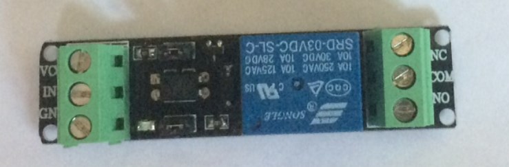
The right side is connected to the high power circuit.
COM = Common line
NC = Normally close
NO = Normally open

The relay will connect or disconnect the COM and NO connections (and disconnect or connect the COM and NC connections).

The left side is connected to the board. Note that I'm using a 3.3v relay as I'm using a 3.3v board.
VCC - 3.3v pin
IN - The logic pin (d6 in the example)
GND

Setting the IN pin to high will connect the switch.

The Android is connected to the board with MQTT.

B4R code (libraries: rESP8266, rESP8266WiFi and rMQTT)
B4X:
Sub Process_Globals
   Public Serial1 As Serial
   Private d1pins As D1Pins
   Private d6 As Pin
   Private mqtt As MqttClient
   Private wifi As ESP8266WiFi
   Private client As WiFiSocket
End Sub

Private Sub AppStart
   Serial1.Initialize(115200)
   Log("AppStart")
   d6.Initialize(d1pins.D6, d6.MODE_OUTPUT)
   d6.DigitalWrite(False)
   If wifi.Connect("dlink") = False Then
     Log("Error connecting to router!")
     Return
   End If
  'broker address is: 192.168.0.6:51042. Change as needed.
   mqtt.Initialize(client.Stream, Array As Byte(192, 168, 0, 6), _
     51042, "esp", "Mqtt_MessageArrived", "Mqtt_Disconnected")
   Connect(0)
End Sub


Sub Connect(unused As Byte)
  If mqtt.Connect = False Then
  Log("trying to connect again")
  CallSubPlus("Connect", 1000, 0)
  Return
  End If
  Log("Connected to broker")
  mqtt.Subscribe("esp", 0)
End Sub

Sub Mqtt_MessageArrived (Topic As String, Payload() As Byte)
   Log("Message arrived. Topic=", Topic, " payload: ", Payload)
   If Topic = "esp" Then
     Dim b As Boolean
     b = Payload(0) = 1
     d6.DigitalWrite(b)
   End If
End Sub

Sub Mqtt_Disconnected
  Log("Disconnected")
  mqtt.Close
  Connect(0)
End Sub

The B4A project is attached. I'm running an external MQTT broker. You can run it in your B4A project if you like.
 

Attachments

  • B4A_Relay.zip
    7.8 KB · Views: 1,327
Last edited:

derez

Expert
Licensed User
Longtime User
Solved - I just had to add "subscribe" to the B4A code...

It works for me but when I added a reply from the esp to B4A it never arrives (the broker sends it).

...
<esp> subscribed to topic <esp> with QoS 0 - MOST_ONE
decode invoked with buffer UnpooledUnsafeDirectByteBuf(ridx: 1, widx: 10, cap: 496)
Received a message of type PUBLISH
onEvent processing messaging event from input ringbuffer ProtocolEvent wrapping PUBLISH
PUBLISH from clientID <myphone> on topic <esp> with QoS LEAST_ONE
send publish message to <esp> on topic <esp>
decode invoked with buffer UnpooledUnsafeDirectByteBuf(ridx: 1, widx: 12, cap: 512)
Received a message of type PUBLISH
onEvent processing messaging event from input ringbuffer ProtocolEvent wrapping PUBLISH
PUBLISH from clientID <esp> on topic <myphone> with QoS MOST_ONE
Received a message of type PINGREQ
...

Working with two Wemos I get the messages both sides.
 
Last edited:

derez

Expert
Licensed User
Longtime User
B4X:
Sub Mqtt_MessageArrived (Topic AsString, Payload() As Byte)
Log("Message arrived. Topic=", Topic, " payload: ", Payload)
If Topic = "esp" Then...
"Topic" is the receiving device,
How can you tell which is the sending device ?I have just included an identifier in the message itself.
 
Last edited:

Erel

B4X founder
Staff member
Licensed User
Longtime User
How can you tell which is the sending device ?I have just included an identifier in the message itself
This is the only way.

Can we send data to arduino(esp8266) without MQTT ?
Yes. There are many ways to communicate with ESP8266. Go over the tutorials.

Just to comment that your electronic circuit setup (shown in the video) is absolutely LETHAL!!
I will add a more clear warning.
 

Cableguy

Expert
Licensed User
Longtime User
Just to comment that your electronic circuit setup (shown in the video) is absolutely LETHAL!!
The full 240 volt AC mains power is exposed underneath the green 3-pole screw connectors on the relay board! If you pick up this circuit board (especially when the lamp is not on) and touch the soldering pins that correspond with the two brown wires, then it could be curtains: Your hand muscles will contract and you won't be able to free yourself. This circuit must really be boxed-in in an enclosure. I recommend to replace this video, because some viewers might not realize the dangers of this setup.

I think this is one of the major dangers in "modern" electronics...
The increasing popularity of development boards like the arduino and the esp8266 and the resulting industry around the breakout boards and shields, have attracted many non-technical enlighten users.
Still, common sense is to be applied, as to everything, and the simple fact that mains is being connected to a bare-board should fire some danger alert brain-zone.
A simple statement will the minimum required, but, in an "proof-of-concept" kind of circuit as the one at hand, more than that would make it a "final-assembly" project... So a compromise has to be done...
A statement about the dangers of mains bring directly connected to the board should be accompanied by a graphical alert!
 

Gaver Powers

Member
Licensed User
Longtime User
I think this is one of the major dangers in "modern" electronics...
The increasing popularity of development boards like the arduino and the esp8266 and the resulting industry around the breakout boards and shields, have attracted many non-technical enlighten users.
Still, common sense is to be applied, as to everything, and the simple fact that mains is being connected to a bare-board should fire some danger alert brain-zone.
A simple statement will the minimum required, but, in an "proof-of-concept" kind of circuit as the one at hand, more than that would make it a "final-assembly" project... So a compromise has to be done...
A statement about the dangers of mains bring directly connected to the board should be accompanied by a graphical alert!

An easy solution would be to utilize 3.3 volts (DC) as the power thru the relay - and illuminate an LED instead of a 220v light bulb.
 

Cableguy

Expert
Licensed User
Longtime User
An easy solution would be to utilize 3.3 volts (DC) as the power thru the relay - and illuminate an LED instead of a 220v light bulb.
Yes, but the idea was/is to show how to control power appliances... You don't need a relay to light up a LED
 
Top