Hi all,
as promised here:
https://www.b4x.com/android/forum/threads/algorithm-first-post-map-a-value-from-one-range-to-another-range-the-simple-way.144391/
... this is a second part of my [algorithm] Code Snippets.
Today I want show to users that never used it, a digital Low-Pass filter.
Low-Pass filter help to smooth signals and remove/decrease the signal noise if any.
This even is used in electronics to remove noise, prevent spikes and more, see RC (Resistor-Condenser) filter.
LPF can be used to filter sensor readings and more.
This is digital but works the same that RC filter in electronic, and you will get the same results.
It is a realtime computed Low Pass Filter that cuts all frequencies above a certain threshold from signal.
Note that this concept is applicable to any language, I used it many times on my old VB6 projects, on Android using B4A, on Desktop using B4J or pure java or C++ code, in Javascript, in python, on Arduino side using Arduino IDE (and C++) or B4R, so this is largely portable and can be applied to any language. What we discuss here today is a concept.
To know how LPF filter works I invite you to get more informations here:
Many thanks to Wikipedia The Free Encyclopedia
What we need to do is follow this formula that I already converted to code:
where:
- INPUT is the current input signal, can be an integer or floating point number, eg. Int, Long, Float, Double
- FILTER is a Float or Double variable (should be a global variable) that indicate the current filtered value
- COEF is a Float or Double variable (should be a global variable if you do not pass as argument) that indicate the filter cutoff and should be from 0.0 to MAXCOEF
- MAXCOEF is a Float or Double variable (should be a global variable) that indicate the max cutoff (by default I always used 1.0)
Here there are some consideration to do:
- Float is perfectly suitable, and speed up a bit a calculation, but using Double you have a double precision. Use it depending on what do you need to do, eg if you filter a sensor, you can even use Float, If you need to filter an audio or other where precision is essential, it is better to always use Double.
- The real only global variable you shoud use here is FILTER because it is used to store the last filtered value that serves to our code in the next iteration of filter calculation.
Note here that I used 'Ceil' function because it round a value to integer, without this sometimes I have values like 499.9999999 to indicate 500 and the final filter output value differ by one unit that original input signal, probably here there is a better way, this worked well on VB6 some ages ago, and the attached demo code is a direct port of VB6 project from my old backups. As I did on VB6 I don't had necessity to Ceil values but all variables are dimensioned as Currency that is a particular variable that support up 64bit.
I admit that is a lot more complicated to explain that really do it , this involves just 3 lines of code as follow:
This to be working need to be called continually at specific time interval passing the current signal value, eg we suppose you read sensors in a loop or by using timers . For this reason it is even called 'Recursive Filter'.
As you can see the algorithm when called (on every iteration) will add a small part of old signal to the current signal, to increase a resolution we multiply the input signal value to a large number, that can be 1000, 10000 and so, then on the end after we used it to calculate a filtered value, we divide back by same number to calculate the OUTPUT value, to simplify it you can do it just this way:
The COEF and MAXCOEF they play the most important role here, MAXCOEF (by default I use 1.0) is the max filter Cutoff coefficient, COEF is the current filter Cutoff that should be from 0.0 to MAXCOEF.
- The more COEF is small (near Zero) the more the INPUT signal will be filtered but it require more time to reach final OUTPUT signal. This result in a smothing signal out.
- COEF shoud be > 0.0 and < MAXCOEF or the filter cannot work
- The more COEF is bigger (but max MAXCOEF) the more the INPUT signal will not be filtered, so with COEF near MAXCOEF (but should be < of MAXCOEF) the OUTPUT value will be pretty EQUAL to original INPUT signal and it require less iteractions to reach the output value. (See in the attached demo the FILTER INTERVENT led that switch ON when the algorithm apply the filter and switch OFF when value reach the right output value and is no more filtered)
I know that division is slow, on this direction on C++ I use the SHIFT Operator, eg instead of multiply I shift left some bit positions (eg shift left 14 bits is like multiply by 1024) and finally shift the result value right by same number of bits, this is faster operation that division. I suppose on B4X too Bit.Shift is faster than division ?
You can even wrap it in a Sub eg. something like this:
Mmmmmm... and what if I need more than one filter, eg. accelerometer return 3 different values, each for axis X, Y, Z ?
Use more than one filter is not a problem, you can easly instantiate array of filters, there is not limit on number of filters you can instantiate, apart your device ram.
You can easly have one or more filters, each that works in background indipendently from others, you can set all with same Cutoff or anyone with it's indipendent Cutoff.
To do this you just need to use an array of filters, eg. suppose you need to filter accelerometer readings (3 values) you can do something like this:
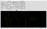
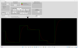
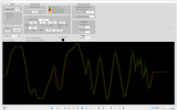
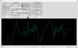
I've attached a B4J project that show it better graphically, draw signals on a Canvas and even compare with a Median Filter (Averaging) to show that (depending on situation) the Low-Pass Filter works better than averaging the values and even have a best refresh, you do not need eg. to sample 10 values and then average it, you have a real value every sample reading that follow the current signal smothing it.
On the attached demo project I've decided to use an integer value (0-1023) and output value as integer to mimic microcontroller ADC, but you can even use floating point values.
Use it is simple, launch, move the INPUT slider and see what happen....
When you tried it, try to decrease the COEF by moving the slider and see what happen by moving INPUT slider, try to move at smaller value (but > Zero) and see what happen moving INPUT slider, try to put COEF to Zero and see what happen by moving INPUT slider.
I developed this tool because it is useful for me to evalutate the filter before use it in new projects, it even simulate a random input and a noise on a input signal. Have fun !!!
as promised here:
https://www.b4x.com/android/forum/threads/algorithm-first-post-map-a-value-from-one-range-to-another-range-the-simple-way.144391/
... this is a second part of my [algorithm] Code Snippets.
Today I want show to users that never used it, a digital Low-Pass filter.
Low-Pass filter help to smooth signals and remove/decrease the signal noise if any.
This even is used in electronics to remove noise, prevent spikes and more, see RC (Resistor-Condenser) filter.
LPF can be used to filter sensor readings and more.
This is digital but works the same that RC filter in electronic, and you will get the same results.
It is a realtime computed Low Pass Filter that cuts all frequencies above a certain threshold from signal.
Note that this concept is applicable to any language, I used it many times on my old VB6 projects, on Android using B4A, on Desktop using B4J or pure java or C++ code, in Javascript, in python, on Arduino side using Arduino IDE (and C++) or B4R, so this is largely portable and can be applied to any language. What we discuss here today is a concept.
To know how LPF filter works I invite you to get more informations here:
Many thanks to Wikipedia The Free Encyclopedia
What we need to do is follow this formula that I already converted to code:
B4X:
FILTER = Ceil((INPUT * COEF) + (FILTER * (MAXCOEF - COEF)))- INPUT is the current input signal, can be an integer or floating point number, eg. Int, Long, Float, Double
- FILTER is a Float or Double variable (should be a global variable) that indicate the current filtered value
- COEF is a Float or Double variable (should be a global variable if you do not pass as argument) that indicate the filter cutoff and should be from 0.0 to MAXCOEF
- MAXCOEF is a Float or Double variable (should be a global variable) that indicate the max cutoff (by default I always used 1.0)
Here there are some consideration to do:
- Float is perfectly suitable, and speed up a bit a calculation, but using Double you have a double precision. Use it depending on what do you need to do, eg if you filter a sensor, you can even use Float, If you need to filter an audio or other where precision is essential, it is better to always use Double.
- The real only global variable you shoud use here is FILTER because it is used to store the last filtered value that serves to our code in the next iteration of filter calculation.
Note here that I used 'Ceil' function because it round a value to integer, without this sometimes I have values like 499.9999999 to indicate 500 and the final filter output value differ by one unit that original input signal, probably here there is a better way, this worked well on VB6 some ages ago, and the attached demo code is a direct port of VB6 project from my old backups. As I did on VB6 I don't had necessity to Ceil values but all variables are dimensioned as Currency that is a particular variable that support up 64bit.
I admit that is a lot more complicated to explain that really do it
B4X:
'////////////////// THIS IS THE MOST IMPORTANT PART OF THIS CODE /////////////////

' LOW-PASS FILTER
INPUT = INPUT * 1000
FILTER = Ceil((INPUT * COEF) + (FILTER * (MAXCOEF - COEF)))
OUTPUT = FILTER / 1000

'/////////////////////////////////////////////////////////////////////////////////
This to be working need to be called continually at specific time interval passing the current signal value, eg we suppose you read sensors in a loop or by using timers . For this reason it is even called 'Recursive Filter'.
As you can see the algorithm when called (on every iteration) will add a small part of old signal to the current signal, to increase a resolution we multiply the input signal value to a large number, that can be 1000, 10000 and so, then on the end after we used it to calculate a filtered value, we divide back by same number to calculate the OUTPUT value, to simplify it you can do it just this way:
B4X:
FILTER = Ceil(((INPUT * 1000) * COEF) + (FILTER * (MAXCOEF - COEF)))
OUTPUT = FILTER / 1000- The more COEF is small (near Zero) the more the INPUT signal will be filtered but it require more time to reach final OUTPUT signal. This result in a smothing signal out.
- COEF shoud be > 0.0 and < MAXCOEF or the filter cannot work
- The more COEF is bigger (but max MAXCOEF) the more the INPUT signal will not be filtered, so with COEF near MAXCOEF (but should be < of MAXCOEF) the OUTPUT value will be pretty EQUAL to original INPUT signal and it require less iteractions to reach the output value. (See in the attached demo the FILTER INTERVENT led that switch ON when the algorithm apply the filter and switch OFF when value reach the right output value and is no more filtered)
I know that division is slow, on this direction on C++ I use the SHIFT Operator, eg instead of multiply I shift left some bit positions (eg shift left 14 bits is like multiply by 1024) and finally shift the result value right by same number of bits, this is faster operation that division. I suppose on B4X too Bit.Shift is faster than division ?
You can even wrap it in a Sub eg. something like this:
B4X:
Public FILTER As Float ' Shoud be global to store the value
Public MAX_COEF As Float = 1.0

Private Sub Filter(Value as Float, Coef As Float, MaxCoef As Float) As Float
    Value = Value * 1000
    FILTER = Ceil((Value * Coef) + (FILTER * (MaxCoef - Coef)))
    Return FILTER / 1000
End Sub

Sub Timer1_Tick
     Dim SensorRead As Float = ReadSensorSub() ' Call the sub that read sensor
     SensorRead = Filter(SensorRead, 0.2, MAX_COEF)  ' 0.2 is the Cutoff, small values apply more filter to original signal
     Log("Filtered value: " & SensorRead)
End Sub
Mmmmmm... and what if I need more than one filter, eg. accelerometer return 3 different values, each for axis X, Y, Z ?
Use more than one filter is not a problem, you can easly instantiate array of filters, there is not limit on number of filters you can instantiate, apart your device ram.
You can easly have one or more filters, each that works in background indipendently from others, you can set all with same Cutoff or anyone with it's indipendent Cutoff.
To do this you just need to use an array of filters, eg. suppose you need to filter accelerometer readings (3 values) you can do something like this:
B4X:
Public FILTER(3) As Float ' Instantiate more than one filter. Shoud be global to store the value
Public MAX_COEF As Float = 1.0 ' We can use this in common for all filters or different for each filter

Private Sub Filter(Index As Int, Value as Float, Coef As Float, MaxCoef As Float) As Float
    Value = Value * 1000
    FILTER(Index) = Ceil((Value * Coef) + (FILTER(Index) * (MaxCoef - Coef)))
    Return FILTER(Index) / 1000
End Sub

Sub Timer1_Tick
     Dim XRead As Float = ReadSensorSub(X) ' Call the sub that read sensor, request X value
     Dim YRead As Float = ReadSensorSub(Y) ' Call the sub that read sensor, request Y value
     Dim ZRead As Float = ReadSensorSub(Z) ' Call the sub that read sensor, request Z value

     ' We use here the same cutoff for all 3 filters but we can use it different for each
     XRead = Filter(0, XRead, 0.2, MAXCOEF)  ' 0.2 is the Cutoff, small values apply more filter to original signal
     YRead = Filter(1, YRead, 0.2, MAXCOEF)  ' 0.2 is the Cutoff, small values apply more filter to original signal
     ZRead = Filter(2, ZRead, 0.2, MAXCOEF)  ' 0.2 is the Cutoff, small values apply more filter to original signal

     Log("Filtered values: " & XRead & "," & YRead & "," & ZRead)
End Sub
I've attached a B4J project that show it better graphically, draw signals on a Canvas and even compare with a Median Filter (Averaging) to show that (depending on situation) the Low-Pass Filter works better than averaging the values and even have a best refresh, you do not need eg. to sample 10 values and then average it, you have a real value every sample reading that follow the current signal smothing it.
On the attached demo project I've decided to use an integer value (0-1023) and output value as integer to mimic microcontroller ADC, but you can even use floating point values.
Use it is simple, launch, move the INPUT slider and see what happen....
When you tried it, try to decrease the COEF by moving the slider and see what happen by moving INPUT slider, try to move at smaller value (but > Zero) and see what happen moving INPUT slider, try to put COEF to Zero and see what happen by moving INPUT slider.
I developed this tool because it is useful for me to evalutate the filter before use it in new projects, it even simulate a random input and a noise on a input signal. Have fun !!!
Attachments
Last edited:

