tres belle!
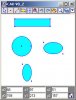
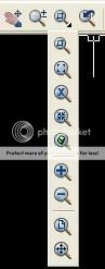
some very nice features, great icons too
also well organised programming style, very nice
but
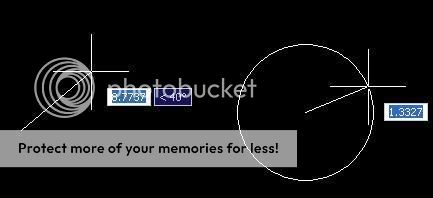
1 - data structure is over complex, why do u need an array count of how many lines a point belongs to and then an array indexing those other lines?
In my mind u should only need array x1(),y1(),x2(),y2(),color()
incidentaly u would also need someway to store a floodfill. this can be done using the line format with the extra provision that if say x2,y2 =(-999,-999) then there is a floodfill done at x1,y1
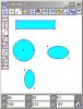
2- too much screen taken up by those lovely icons - many like set up, load save etc dont need to be taking up screen area all the time
some very nice features, great icons too
also well organised programming style, very nice
but
1 - data structure is over complex, why do u need an array count of how many lines a point belongs to and then an array indexing those other lines?
In my mind u should only need array x1(),y1(),x2(),y2(),color()
incidentaly u would also need someway to store a floodfill. this can be done using the line format with the extra provision that if say x2,y2 =(-999,-999) then there is a floodfill done at x1,y1
2- too much screen taken up by those lovely icons - many like set up, load save etc dont need to be taking up screen area all the time
Last edited:
")