If you want more FLASH memory space (say 128K flash), need more RAM (how about 20K), would like your program to run a little faster, or simply want to play around with a different micro-controller family, then have a go at this.
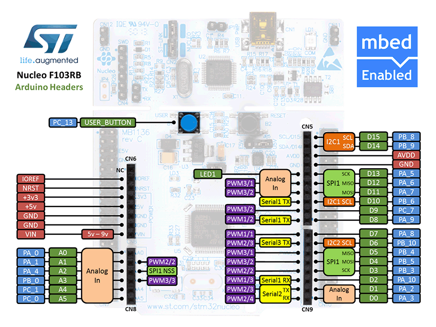
The included PDF document "How to Implement STM32 into B4R.PDF" contains the many steps required to get B4R to compile, upload and run code for a STM32F103RB Nucleo evaluation board.

Download the PDF document and get started.
Note:
Now revised 15th December 2016
Improved B4R integration using the existing STM32 library define
_VARIANT_ARDUINO_STM32_
instead of my own define
USING_STM32.
Now revised 11th August 2020
No need to alter the B4R file, Now included in B4R distribution.
See revised "How to Implement STM32 into B4R" document now
up to date with current distribution of STM32 Library.
The included PDF document "How to Implement STM32 into B4R.PDF" contains the many steps required to get B4R to compile, upload and run code for a STM32F103RB Nucleo evaluation board.
Download the PDF document and get started.
Note:
Now revised 15th December 2016
Improved B4R integration using the existing STM32 library define
_VARIANT_ARDUINO_STM32_
instead of my own define
USING_STM32.
Now revised 11th August 2020
No need to alter the B4R file, Now included in B4R distribution.
See revised "How to Implement STM32 into B4R" document now
up to date with current distribution of STM32 Library.
Attachments
Last edited: