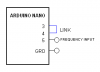
The Arduino generates an accurate 1 second time base for the counter by cascading timer0 and timer2. Part of the B4R code is in C for setting the timers/counters of the Atmega, this way the accuracy is determent by the 16 MHz crystal. The link between digital inputs 3 and 4 connects the output of timer2, 250 Hz, to input of timer0. The software uses the output of timer0 (1Hz) when go positive to start the count of frequency input to timer1. Timer1 is a 16 bits timer, it overflows at the count of 2 power of 16, that in turn advances over-flow register. At the end of the 1 second the 16 bit register is recorded.
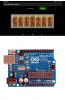
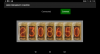
The Arduino sends via OTG (On The Go) cable or adaptor 1 byte as a key + 3 bytes of the measured frequency. The specs recommend up to 6 MHz, I tested it at 2 MHz. The Android app display 0 to 9 images of nixie tubes.
The Arduino sends via OTG (On The Go) cable or adaptor 1 byte as a key + 3 bytes of the measured frequency. The specs recommend up to 6 MHz, I tested it at 2 MHz. The Android app display 0 to 9 images of nixie tubes.