B4R Question Push notification with my intercom door. Thanks for you help. (Solved)

jvrh_1

Active Member
Licensed User
Good morning. I need your help again. I am starting with B4R and I have some doubts.

I would want that when I receive a call in my home intercom door, I receive a push message notification in my mobile phone.

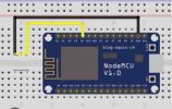
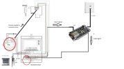
To check it, I have develop a B4R app with a NodeMCU ESP8266 wifi (chip 2102 drive). This board send the push notification. In the other side, I have develop another App with B4A to received the notification. Works perfectly!. To make it, i have conected the GND pin with the D3 pin manually (I have not got a switch botton now). When I conect this wires, all works perfectly. See attached image.


Now, I want that It Works with my home intercom door. This is the model: FERMAX 6201 https://www.tdtprofesional.com/blog/manual-de-instalacion-para-el-kit-6201-de-fermax/

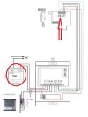
In the manual appears that it Works with 12V in VCA. I have thinked that I could conect the board (pin D3) with the wire number 4. This wire is the buzzer of the home intercom door at house and It will activated when the user press the button, but I do not knwo if I can conect the wire directly to the board because it has got 12V in VCA. What can I do? Thanks a lot.

Sorry. My English skill is not the best.
 

Attachments

  • ESQUEMA.jpeg
    ESQUEMA.jpeg
    77.8 KB · Views: 122
  • TELEFONILLO.jpg
    TELEFONILLO.jpg
    52.1 KB · Views: 127

jvrh_1

Active Member
Licensed User
También ten en cuenta que lo que medirás en CA será el valor RMS. Esto significa que será (Amplitud de la onda)/(Raíz cuadrada de 2). De esta forma se puede calcular la amplitud del voltaje CA.
Hola, nuevamente ya recibí el convertidor Ac a Dc y he instalado todos los componentes siguiendo el esquema adjunto. Cuando toqué el timbre recibí la notificación en la aplicación del teléfono B4A después de 30 segundos aproximadamente. Todo bien. Sin embargo, después de un tiempo, si vuelvo a llamar, no recibo ningún mensaje. Tengo que desconectar el ESP8266 del enchufe USB y volver a conectarlo. Si lo hago, empiezo a recibir todas las notificaciones que no llegaron anteriormente, juntas. No es necesario abrir mi aplicación B4A en mi teléfono. Solo que tengo que desconectar y volver a enchufar el ES8266 y lo recibí nuevamente. ¿Alguien sabe qué está pasando aquí? Utilicé el multímetro para medir el voltaje del anillo y me envía 5-8 voltios en DC aproximadamente...

Parece que la placa se congela, pero esto no es posible porque mientras tanto, la placa está trabajando con otras funciones. Por ejemplo, si envío el comando para encender o apagar los relevadores, responde y lo hace perfectamente.

B4A simplyfied code (Thanks to @José J. Aguilar )

B4X:
#Region Project Attributes
    #AutoFlushLogs: True
    #CheckArrayBounds: True
    #StackBufferSize: 600
#End Region

Sub Process_Globals
    Public Serial1 As Serial
    Private wifi As ESP8266WiFi
    Private astream As AsyncStreams
    Private d1 As D1Pins
    Private btn As Pin
    Private eol() As Byte = Array As Byte(13, 10)
    Private MQTT As MqttClient
    Private MQTTUser As String = ""
    Private MQTTPassword As String = ""
    Private MQTTBroker As String = "test.mosquitto.org"'change for other broker
    Private MQTTPort As Int = 1883
    Private WiFiStr As WiFiSocket
    Private State As Boolean
    Private BC As ByteConverter
    Private API_KEY() As Byte = "XXXXXXXXXXX"
End Sub

Private Sub AppStart
    Delay(500)
    Serial1.Initialize(115200)
    Log("AppStart")   
'...............................................................................................   

    
    btn.Initialize(d1.D3, btn.MODE_INPUT)
    btn.AddListener("btn_StateChanged")
    
    
'...............................................................................................   
    'Connect to local WiFi Access Point
    If wifi.Connect2("xxxxxxx", "xxxxxx") Then'<---change for your wifi router AP
        Log("Connected to Router WiFi --> Ok")'connected
        Log("ESP8266 IP --> ", wifi.LocalIp)'IP ESP
        'Connect to CloudMQTT broker
        Dim clientId As String = "ESP-" + Rnd(0, 999999999)'create unique id
        MQTT.Initialize2(WiFiStr.stream, MQTTBroker, MQTTPort, clientId, "MQTT_MessageArrived", "MQTT_Disconnected")               
        MQTT_Connect(0)'--->sub connect
    Else
        Log("Connection wifi problem!")
        Return
    End If
    
End Sub

Sub Server_NewConnection (NewSocket As WiFiSocket)
    Log("Client connected")   
    astream.Initialize(NewSocket.Stream, "astream_NewData", "astream_Error")       
End Sub

Sub Astream_NewData (Buffer() As Byte)
    Log("Received: ", Buffer)
End Sub

Sub AStream_Error
    Log("Error")
    
End Sub

'Mqtt connect/reconnect
Sub MQTT_Connect(Unused As Byte)
    If MQTT.Connect = False Then'if do not connect...       
        Dim mo As MqttConnectOptions
        mo.Initialize(MQTTUser, MQTTPassword)
        MQTT.Connect2(mo)
        CallSubPlus("MQTT_Connect", 1000, 0)'...Tray to reconnect after 1 sec.
    Else
        Log("Connected to broker --> Ok")'All ok
        
        
    End If
End Sub


'Disconnect
Sub MQTT_Disconnected
    Log("Mqtt Disconnct")
    MQTT.Close
End Sub

'AQUÍ LO DEL TELEFONILLO PARA MANDAR PUSH
'_______________________________________________
Sub Btn_StateChanged (ESTADO As Boolean)
    If State = False Then
        SendMessage("general", "¡Llaman al timbre!", "This is the body")
    End If
End Sub
Sub JobDone (jr As JobResult)
    Log("JobDone: ", jr.JobName)
    Log("Success: ", jr.Success)
    If jr.JobName = "ios_general" Then
        'send the ios message
        SendMessage("ios_general", "¡Llaman al timbre!", "This is the body")
    End If
End Sub

Private Sub SendMessage(Topic() As Byte, Title() As Byte, Body() As Byte)
    'Dim BC As ByteConverter
    HttpJob.Initialize(BC.StringFromBytes(Topic))
    Dim buffer(300) As Byte 'must be large enough to hold the message payload
    Dim raf As RandomAccessFile
    raf.Initialize(buffer, True)
    WriteBytes(raf, "{""data"":{""title"":""")
    WriteBytes(raf, Title)
    WriteBytes(raf, """,""body"":""")
    WriteBytes(raf, Body)
    WriteBytes(raf, """}")
    'end of data
    WriteBytes(raf, ",""to"":""\/topics\/")
    WriteBytes(raf, Topic)
    WriteBytes(raf, """")
    WriteBytes(raf, ",""priority"": 10")
    If BC.StartsWith(Topic, "ios_") Then
        WriteBytes(raf, ",""notification"": {""title"": """)
        WriteBytes(raf, Title)
        WriteBytes(raf, """,""body"":""")
        WriteBytes(raf, Body)
        WriteBytes(raf, """, ""sound"": ""default""}")
    End If
    WriteBytes(raf, "}")
    HttpJob.AddHeader("Authorization", JoinBytes(Array("key=".GetBytes, API_KEY)))
    HttpJob.AddHeader("Content-Type", "application/json")
    Log("stack: ", StackBufferUsage, ", buffer size:", raf.CurrentPosition)
    HttpJob.Post("https://fcm.googleapis.com/fcm/send", BC.SubString2(buffer, 0, raf.CurrentPosition))
End Sub

Private Sub WriteBytes(raf As RandomAccessFile, Data() As Byte)
    raf.WriteBytes(Data, 0, Data.Length, raf.CurrentPosition)
End Sub
 

Attachments

  • TELEFONILLO CON ENTRADA.jpg
    TELEFONILLO CON ENTRADA.jpg
    166.9 KB · Views: 87
Last edited:
Upvote 0

hatzisn

Well-Known Member
Licensed User
Longtime User
Hola, nuevamente ya recibí el convertidor Ac a Dc y he instalado todos los componentes siguiendo el esquema adjunto. Cuando toqué el timbre recibí la notificación en la aplicación del teléfono B4A después de 30 segundos aproximadamente. Todo bien. Sin embargo, después de un tiempo, si vuelvo a llamar, no recibo ningún mensaje. Tengo que desconectar el ESP8266 del enchufe USB y volver a conectarlo. Si lo hago, empiezo a recibir todas las notificaciones que no llegaron anteriormente, juntas. No es necesario abrir mi aplicación B4A en mi teléfono. Solo que tengo que desconectar y volver a enchufar el ES8266 y lo recibí nuevamente. ¿Alguien sabe qué está pasando aquí? Utilicé el multímetro para medir el voltaje del anillo y me envía 5-8 voltios en DC aproximadamente...

Parece que la placa se congela, pero esto no es posible porque mientras tanto, la placa está trabajando con otras funciones. Por ejemplo, si envío el comando para encender o apagar los relevadores, responde y lo hace perfectamente.

See in my signature (My contributions to the community) the tutorial in B4J to stop IPv6 in your PC for push notifications (linux or windows). This worked for me for definite delivery of push notifications. Maybe it will work for you too.
 
Upvote 0

jvrh_1

Active Member
Licensed User
Upvote 0

hatzisn

Well-Known Member
Licensed User
Longtime User
No, this one:

 
Upvote 0

jvrh_1

Active Member
Licensed User
No, this one:

I have read this but, I have not got Windows, Linux... I only use the board with the BJ4R and my mobile phone with B4A.
 
Upvote 0

hatzisn

Well-Known Member
Licensed User
Longtime User
I have read this but, I have not got Windows, Linux... I only use the board with the BJ4R and my mobile phone with B4A.

How do you send the push notification to the B4A app. Don't you use the new B4J software by @Erel in a Linux or windows based computer? You could combine the software by @Erel with a webapp and make an http request there in order to send the push notification. Don't you do that? How can you send a push notification differently?
 
Upvote 0

jvrh_1

Active Member
Licensed User
¿Cómo se envía la notificación push a la aplicación B4A? ¿No utilizas el nuevo software B4J de @Erel en una computadora con Linux o Windows? Puede combinar el software de @Erel con una aplicación web y realizar una solicitud http allí para enviar la notificación push. ¿No haces eso? ¿Cómo se puede enviar una notificación push de manera diferente?
I haven't got a server application to hosting any B4J app. I only use an app made with B4R in the board. This app send messages using mqtt to a broker (for example mosquitto). After that, my app in B4A download the message notification using Firebase module.
 
Upvote 0

XorAndOr

Active Member
Licensed User
Longtime User
I used the translator, and if the "translator" is not wrong...you have a problem when you resend messages
1) first of all you have to correct the sub button because it is "State" and not "ESTADO"
your code B4R Post #21
B4R:
Sub Btn_StateChanged (ESTADO As Boolean)
    If State = False Then
        SendMessage("general", "¡Llaman al timbre!", "This is the body")
    End If
End Sub
if State is True...don't resend the message put a log to be sure and press the button to verify.
2) In initialize you have to put the "pull up" method
B4R:
btn.Initialize(d1.D3, btn.MODE_INPUT_PULLUP) 'Using the internal pull up resistor to prevent the pin from floating.
btn.AddListener("Btn_StateChanged")
3) if I understood/mistranslated...ignore this post.
 
Last edited:
Upvote 0

jvrh_1

Active Member
Licensed User
I used the translator, and if the "translator" is not wrong...you have a problem when you resend messages
1) first of all you have to correct the sub button because it is "State" and not "ESTADO"
your code B4R Post #21
B4R:
Sub Btn_StateChanged (ESTADO As Boolean)
    If State = False Then
        SendMessage("general", "¡Llaman al timbre!", "This is the body")
    End If
End Sub
if State is True...don't resend the message put a log to be sure and press the button to verify.
2) In initialize you have to put the "pull up" method
B4R:
btn.Initialize(d1.D3, btn.MODE_INPUT_PULLUP) 'Using the internal pull up resistor to prevent the pin from floating.
btn.AddListener("Btn_StateChanged")
3) if I understood/mistranslated...ignore this post.
I am very confused. I have checked again with multimeter the output signal of my intercom and when I am pressing the button apears 4-8 v and when I am realising this appears 0 v. But, In the log of the B4R appears status 0 and status 1 all the time changing. Can somebody review my connections schema? I do not understand anything.
 

Attachments

  • WhatsApp Image 2023-08-23 at 13.24.42.jpeg
    WhatsApp Image 2023-08-23 at 13.24.42.jpeg
    351.4 KB · Views: 91
Upvote 0

jvrh_1

Active Member
Licensed User
I used the translator, and if the "translator" is not wrong...you have a problem when you resend messages
1) first of all you have to correct the sub button because it is "State" and not "ESTADO"
your code B4R Post #21
B4R:
Sub Btn_StateChanged (ESTADO As Boolean)
    If State = False Then
        SendMessage("general", "¡Llaman al timbre!", "This is the body")
    End If
End Sub
if State is True...don't resend the message put a log to be sure and press the button to verify.
2) In initialize you have to put the "pull up" method
B4R:
btn.Initialize(d1.D3, btn.MODE_INPUT_PULLUP) 'Using the internal pull up resistor to prevent the pin from floating.
btn.AddListener("Btn_StateChanged")
3) if I understood/mistranslated...ignore this post.
I checked it and does not happend.
B4X:
btn.Initialize(d1.D3, btn.MODE_INPUT_PULLUP) 'Using the internal pull up resistor to prevent the pin from floating.
btn.AddListener("Btn_StateChanged")

And in relation with this part. I use "ESTADO" because I use "State" to another signal to open or close some doors.

B4X:
Sub Btn_StateChanged (ESTADO As Boolean)
    If State = False Then
        SendMessage("general", "¡Llaman al timbre!", "This is the body")
    End If
End Sub
 
Upvote 0

jvrh_1

Active Member
Licensed User
I checked it and does not happend.
B4X:
btn.Initialize(d1.D3, btn.MODE_INPUT_PULLUP) 'Using the internal pull up resistor to prevent the pin from floating.
btn.AddListener("Btn_StateChanged")

And in relation with this part. I use "ESTADO" because I use "State" to another signal to open or close some doors.

B4X:
Sub Btn_StateChanged (ESTADO As Boolean)
    If State = False Then
        SendMessage("general", "¡Llaman al timbre!", "This is the body")
    End If
End Sub

I have cheked all again and the problem is in the connections. If I connect manually gnd with my D3 pin, I recieve notifications perfectly. :(
 
Upvote 0

bdunkleysmith

Active Member
Licensed User
Longtime User
I have been following your project with interest and would like to offer this as something to try to fix the "status 0 and status 1 all the time changing" problem.

While you may measure 0V on the output of the 12VAC - 5VDC converter when the button is not pressed, I wonder if the output is what I would describe as "tied" to ground or if it is "floating" in that state. This would create the possibility of unwanted signal pick up that may be causing the continual change from status 0 to status 1.

To tie the D3 input to ground and minimise the unwanted pick up I would suggest putting a resistor between D3 and GND, say 1kohm.

Another possibility is that because the load on the output presented by D3 on the ESP8266 is so low that there is residual output from the 12VAC - 5VDC converter for some time after the button is released. It may be a better solution to have the output of the 12VAC - 5VDC converter drive a relay and connect the normally open contacts of the relay to D3 (set to pull up input mode) and GND so it replicates your manual method of triggering the notification.
 
Upvote 0

jvrh_1

Active Member
Licensed User
I have been following your project with interest and would like to offer this as something to try to fix the "status 0 and status 1 all the time changing" problem.

While you may measure 0V on the output of the 12VAC - 5VDC converter when the button is not pressed, I wonder if the output is what I would describe as "tied" to ground or if it is "floating" in that state. This would create the possibility of unwanted signal pick up that may be causing the continual change from status 0 to status 1.

To tie the D3 input to ground and minimise the unwanted pick up I would suggest putting a resistor between D3 and GND, say 1kohm.

Another possibility is that because the load on the output presented by D3 on the ESP8266 is so low that there is residual output from the 12VAC - 5VDC converter for some time after the button is released. It may be a better solution to have the output of the 12VAC - 5VDC converter drive a relay and connect the normally open contacts of the relay to D3 (set to pull up input mode) and GND so it replicates your manual method of triggering the notification.

I have been following your project with interest and would like to offer this as something to try to fix the "status 0 and status 1 all the time changing" problem.

While you may measure 0V on the output of the 12VAC - 5VDC converter when the button is not pressed, I wonder if the output is what I would describe as "tied" to ground or if it is "floating" in that state. This would create the possibility of unwanted signal pick up that may be causing the continual change from status 0 to status 1.
I will put a resistor. I think that is very convenient. Good idea. Thanks.

Another possibility is that because the load on the output presented by D3 on the ESP8266 is so low that there is residual output from the 12VAC - 5VDC converter for some time after the button is released.
Certanly, It is happening. I measure it, and when I release de button, the voltage decrease slowly.

It may be a better solution to have the output of the 12VAC - 5VDC converter drive a relay and connect the normally open contacts of the relay to D3 (set to pull up input mode) and GND so it replicates your manual method of triggering the notification
Yes, I already proved it and it did not work. Attached my diagram.

Finally, I made a separate circuit. I modified the street button, so when somebody press it, it activate the intercom and It activate the ESP circuit board too. I need to use the wire number 3 of my intercom to pass the signal so, I remove it from intercom and I connected it to the power supply directly. At this momento it is working, nevertheless I will putt he ressistor that you say to absorbe possible interferences. Attached my diagram. It’s not the best solution, but I can’t find a better one.
Thank you very much for your help. Without It I could never have managed to finish the project.
 

Attachments

  • ESQUEMA DEFINITIVO.jpg
    ESQUEMA DEFINITIVO.jpg
    93.1 KB · Views: 73
  • TELEFONILLO CON RELE.jpg
    TELEFONILLO CON RELE.jpg
    189.9 KB · Views: 82
Upvote 0

hatzisn

Well-Known Member
Licensed User
Longtime User
I will put a resistor. I think that is very convenient. Good idea. Thanks.


Certanly, It is happening. I measure it, and when I release de button, the voltage decrease slowly.


Yes, I already proved it and it did not work. Attached my diagram.

Finally, I made a separate circuit. I modified the street button, so when somebody press it, it activate the intercom and It activate the ESP circuit board too. I need to use the wire number 3 of my intercom to pass the signal so, I remove it from intercom and I connected it to the power supply directly. At this momento it is working, nevertheless I will putt he ressistor that you say to absorbe possible interferences. Attached my diagram. It’s not the best solution, but I can’t find a better one.
Thank you very much for your help. Without It I could never have managed to finish the project.

D3 is also (at least in WeMos D1 Mini) a pull up by itsself. The pin you have connected the cable in the Relay from D3 is the normally closed. I have taken a look in this component datasheet. If no one is pressing the button then the Buck Converter (12V->5V) gives 0 volts so the switch of the Finder relay remains to normally closed. So obviously D3 is brought to 0 volts. When someone presses the button in the doorbell outside it sends 12V AC to the back converter and this converter gives 5V to the relay which moves the switch to normally open and thus D3 is brought to high by the internall pull up resistor. You will have to check if (State As Boolean) in the code bellow is brought to true... Since you say it is working I suppose you are you doing this... Right? Also If I were you, as @bdunkleysmith says, I would try to connect a 10K resistor to the positive of the buck converter and the ground. Sometimes it worths trying also to connect the two grounds although in this case my understanding is that you don't have to... You have put homework to me and I am already checking my video door bell to do the same... Mine is 20V DC. :)

B4X:
Sub Process_Globals

    Public Serial1 As Serial

    'These are irrelevant for you - they refer to a distance measurement component
    '----------------------------------------------------
    Private triggerpin,echopin As Pin
    Dim pulsduration As ULong             'Pulse Width on Echo Pin (High to Low)
    Dim distance As Double
    '----------------------------------------------------
 
    Private buttonout As Pin
    Dim BounceMillis As ULong = 0
    Dim BounceDelay As ULong = 10
End Sub

Private Sub AppStart

    Serial1.Initialize(9600)
    Log("AppStart")

    'Configure Pins connection between Arduino and Distance Sensor
    triggerpin.Initialize(42,triggerpin.MODE_OUTPUT)
    echopin.Initialize(43,echopin.MODE_INPUT)
    echopin.DigitalWrite(False)

    'Enable trigger with a button
    buttonout.Initialize(30, buttonout.MODE_INPUT_PULLUP)
    buttonout.AddListener("buttonout_StateChanged")
 
End Sub

Private Sub buttonout_StateChanged(State As Boolean)
 
    ' In my code it activates when it is brought to low
    ' For your case you have to change the False To True in the following code
    If State = False Then
        If Millis - BounceMillis < BounceDelay Then
            Return
        Else
            Log("-------------------------------------------------------")
            Log(GetCurrentRunningHour(Millis))
            Log("Button Pressed")
            Log("Checking distance")
            CheckDistance
            BounceMillis = Millis
        End If
    End If
 
End Sub

Sub CheckDistance
     '......................................
End Sun
 
Last edited:
Upvote 0

jvrh_1

Active Member
Licensed User
D3 is also (at least in WeMos D1 Mini) a pull up by itsself. The pin you have connected the cable in the Relay from D3 is the normally closed. I have taken a look in this component datasheet. If no one is pressing the button then the Buck Converter (12V->5V) gives 0 volts so the switch of the Finder relay remains to normally closed. So obviously D3 is brought to 0 volts. When someone presses the button in the doorbell outside it sends 12V AC to the back converter and this converter gives 5V to the relay which moves the switch to normally open and thus D3 is brought to high by the internall pull up resistor. You will have to check if (State As Boolean) in the code bellow is brought to true... Since you say it is working I suppose you are you doing this... Right? Also If I were you, as @bdunkleysmith says, I would try to connect a 10K resistor to the positive of the buck converter and the ground. Sometimes it worths trying also to connect the two grounds although in this case my understanding is that you don't have to... You have put homework to me and I am already checking my video door bell to do the same... Mine is 20V DC. :)

B4X:
Sub Process_Globals

    Public Serial1 As Serial

    'These are irrelevant for you - they refer to a distance measurement component
    '----------------------------------------------------
    Private triggerpin,echopin As Pin
    Dim pulsduration As ULong             'Pulse Width on Echo Pin (High to Low)
    Dim distance As Double
    '----------------------------------------------------
 
    Private buttonout As Pin
    Dim BounceMillis As ULong = 0
    Dim BounceDelay As ULong = 10
End Sub

Private Sub AppStart

    Serial1.Initialize(9600)
    Log("AppStart")

    'Configure Pins connection between Arduino and Distance Sensor
    triggerpin.Initialize(42,triggerpin.MODE_OUTPUT)
    echopin.Initialize(43,echopin.MODE_INPUT)
    echopin.DigitalWrite(False)

    'Enable trigger with a button
    buttonout.Initialize(30, buttonout.MODE_INPUT_PULLUP)
    buttonout.AddListener("buttonout_StateChanged")
 
End Sub

Private Sub buttonout_StateChanged(State As Boolean)
 
    ' In my code it activates when it is brought to low
    ' For your case you have to change the False To True in the following code
    If State = False Then
        If Millis - BounceMillis < BounceDelay Then
            Return
        Else
            Log("-------------------------------------------------------")
            Log(GetCurrentRunningHour(Millis))
            Log("Button Pressed")
            Log("Checking distance")
            CheckDistance
            BounceMillis = Millis
        End If
    End If
 
End Sub

Sub CheckDistance
     '......................................
End Sun
Firstly, Thanks for you help. I don't know anything of electronics and It is very difficult for me. Although, I am reading a lot to understand some concepts. For example, the relay solution. I tried to implement this and does not worked. Efectively, in the picture, D3 is connected to default open, but, at thath moment I proved to connect to the other output of relay to check it, but I got the same result.

I say that is working because I have implemented another more simply solution. I do not use the intercom to recive signal of the buffer wire. I have modified the button of the street device to enabled a second circuit that does not pass throught out the intercom circuit. With this buton, now I activate two different and independient circuits. One of them is for the intercomunicator (like always) and in the other hand, open or close (press down or up) the circuit of the ESP (like a simple switch button). See new image.

But now, I need your help in relation with the resistor. Can you mark in my diagram where I have to put it? You say that the resistor have to be of 10Kohm but @bdunkleysmith says that 1Kohm. What is the correct meassure?

Sometimes, in a random times, I recieve some notifications without press the button and I think that it can be because there may be some interferences because I am using the GND output and I think if I use a resistor this can get better. Is is true?

I also tried to connect D3 with 3V3 output (not with GND), but it didn’t work.

I know I don’t know a lot about electronics, but I’m putting a lot of effort into making up for this. Also, English is not my native language and I find it difficult to express myself clearly.

Can you help me with the resistor, please?
 

Attachments

  • ESQUEMA DEFINITIVO.jpg
    ESQUEMA DEFINITIVO.jpg
    93.1 KB · Views: 82
Upvote 0

jvrh_1

Active Member
Licensed User
D3 is also (at least in WeMos D1 Mini) a pull up by itsself. The pin you have connected the cable in the Relay from D3 is the normally closed. I have taken a look in this component datasheet. If no one is pressing the button then the Buck Converter (12V->5V) gives 0 volts so the switch of the Finder relay remains to normally closed. So obviously D3 is brought to 0 volts. When someone presses the button in the doorbell outside it sends 12V AC to the back converter and this converter gives 5V to the relay which moves the switch to normally open and thus D3 is brought to high by the internall pull up resistor. You will have to check if (State As Boolean) in the code bellow is brought to true... Since you say it is working I suppose you are you doing this... Right? Also If I were you, as @bdunkleysmith says, I would try to connect a 10K resistor to the positive of the buck converter and the ground. Sometimes it worths trying also to connect the two grounds although in this case my understanding is that you don't have to... You have put homework to me and I am already checking my video door bell to do the same... Mine is 20V DC. :)

B4X:
Sub Process_Globals

    Public Serial1 As Serial

    'These are irrelevant for you - they refer to a distance measurement component
    '----------------------------------------------------
    Private triggerpin,echopin As Pin
    Dim pulsduration As ULong             'Pulse Width on Echo Pin (High to Low)
    Dim distance As Double
    '----------------------------------------------------
 
    Private buttonout As Pin
    Dim BounceMillis As ULong = 0
    Dim BounceDelay As ULong = 10
End Sub

Private Sub AppStart

    Serial1.Initialize(9600)
    Log("AppStart")

    'Configure Pins connection between Arduino and Distance Sensor
    triggerpin.Initialize(42,triggerpin.MODE_OUTPUT)
    echopin.Initialize(43,echopin.MODE_INPUT)
    echopin.DigitalWrite(False)

    'Enable trigger with a button
    buttonout.Initialize(30, buttonout.MODE_INPUT_PULLUP)
    buttonout.AddListener("buttonout_StateChanged")
 
Subtítulo final

Subbotón privado_StateChanged (estado como booleano)
 
    ' En mi código se activa cuando se baja
    ' Para su caso, debe cambiar False a True en el siguiente código
    Si Estado = Falso Entonces
        Si Millis - BounceMillis < BounceDelay Entonces
            Devolver
        Demás
            Registro("----------------------------------------------- --------")
            Registro(GetCurrentRunningHour(Millis))
            Registro("Botón presionado")
            Registro("Comprobando distancia")
            Comprobar distancia
            ReboteMillis = Millis
        Terminara si
    Terminara si
 
Subtítulo final

Distancia de verificación secundaria
     '...................................
Sol final
[/CÓDIGO
[/QUOTE]
Lo siento de nuevo y gracias por tu paciencia.
Millis - BounceMillis < BounceDelay  .... What is this? What does it mean? What do you want to get?
 
Upvote 0

hatzisn

Well-Known Member
Licensed User
Longtime User
Firstly, Thanks for you help. I don't know anything of electronics and It is very difficult for me. Although, I am reading a lot to understand some concepts. For example, the relay solution. I tried to implement this and does not worked. Efectively, in the picture, D3 is connected to default open, but, at thath moment I proved to connect to the other output of relay to check it, but I got the same result.

I say that is working because I have implemented another more simply solution. I do not use the intercom to recive signal of the buffer wire. I have modified the button of the street device to enabled a second circuit that does not pass throught out the intercom circuit. With this buton, now I activate two different and independient circuits. One of them is for the intercomunicator (like always) and in the other hand, open or close (press down or up) the circuit of the ESP (like a simple switch button). See new image.

But now, I need your help in relation with the resistor. Can you mark in my diagram where I have to put it? You say that the resistor have to be of 10Kohm but @bdunkleysmith says that 1Kohm. What is the correct meassure?

Sometimes, in a random times, I recieve some notifications without press the button and I think that it can be because there may be some interferences because I am using the GND output and I think if I use a resistor this can get better. Is is true?

I also tried to connect D3 with 3V3 output (not with GND), but it didn’t work.

I know I don’t know a lot about electronics, but I’m putting a lot of effort into making up for this. Also, English is not my native language and I find it difficult to express myself clearly.

Can you help me with the resistor, please?

In order to help you I will save you some time with some brief information. The pins of a microcontroller even if they are set or they are not set they might be hovering in voltage between High and low. High is considered higher than 75% of the highest voltage (3.3V or 5V depending on the microcontroller) and Low is considered bellow 25% of the maximum voltage again (3.3V or 5V depending on the microcontroller) When a pin is hovering between 25% and 75% it is considered in floating State. Depending on your case you might want to pull it at High (that is the maximum voltage) or low and this the Ground. So in order to pull the floating PIN from the floating range to the desired level you'll use a pull up resistor to pull it high or A Pull down resistor to pull it to the Ground. A Pull up resistor is connecting the pin with the microcontroller's maximum voltage pin while a pull down resistor connects the floating PIN to the ground. D3 PIN in WeMos D1 Mini R3 has built in pull up resistor so If you don't set it's voltage or connect it to the ground it will be always held high. So in order to bring the Buck Converter faster to Ground you will need to connect a fairly big resistor between the + that goes to relay and the ground that goes to the relay. Since it goes down slowly I suspect that a capacitor is discharging through a resistor and in this case a fairly small resistor might pull it to ground faster. On the other hand a small resistor like 1K Might cause relay not to work properly. The answer is "trial and error".
 
Last edited:
Upvote 0

jvrh_1

Active Member
Licensed User
In order to help you I will save you some time with some brief information. The pins of a microcontroller even if they are set or they are not set they might be hovering in voltage between High and low. High is considered higher than 75% of the highest voltage (3.3V or 5V depending on the microcontroller) and Low is considered bellow 25% of the maximum voltage again (3.3V or 5V depending on the microcontroller) When a pin is hovering between 25% and 75% it is considered in floating State. Depending on your case you might want to pull it at High (that is the maximum voltage) or low and this the Ground. So in order to pull the floating PIN from the floating range to the desired level you'll use a pull up resistor to pull it high or A Pull down resistor to pull it to the Ground. A Pull up resistor is connecting the pin with the microcontroller's maximum voltage pin while a pull down resistor connects the floating PIN to the ground. D3 PIN in WeMos D1 Mini R3 has built in pull up resistor so If you don't set it's voltage or connect it to the ground it will be always held high. So in order to bring the Buck Converter faster to Ground you will need to connect a fairly big resistor between the + that goes to relay and the ground that goes to the relay. Since it goes down slowly I suspect that a capacitor is discharging through a resistor and in this case a fairly small resistor might pull it to ground faster. On the other hand a small resistor like 1K Might cause relay not to work properly. The answer is "trial and error".
Thanks. Now I know that the problem is in a floating signal, but I have read several forums about it and.. Although I understand the solution, when I implemente it in my real board, It does not work.... I will create a new thread so. Maybe someone will help me make the connections right on my board with some visual schematics because I do not get it. Thanks a lot.
https://www.b4x.com/android/forum/threads/floating-signal-what-can-i-do.149944/
 
Upvote 0

hatzisn

Well-Known Member
Licensed User
Longtime User
Thanks. Now I know that the problem is in a floating signal, but I have read several forums about it and.. Although I understand the solution, when I implemente it in my real board, It does not work.... I will create a new thread so. Maybe someone will help me make the connections right on my board with some visual schematics because I do not get it. Thanks a lot.
https://www.b4x.com/android/forum/threads/floating-signal-what-can-i-do.149944/
Do not jump into conclusions yet. This is the opinion of an amateur, me. Have a search also about the discharging of the capacitor and ask a professional's opinion about both in facebook or specialized pages in web. There a lot of web pages and facebook groups about electronics. Tip: Describe everything you have done with pictures also.
 
Last edited:
Upvote 0

jvrh_1

Active Member
Licensed User
No saques conclusiones precipitadas todavía. Esta es la opinión de un aficionado, yo. Haz una búsqueda también sobre la descarga del condensador y pide opinión a un profesional al respecto tanto en facebook como en páginas web especializadas. Hay muchas páginas web y grupos de facebook sobre electrónica. Consejo: Describe también todo lo que has hecho con la imagen.
I think that the problem is the floating signal as you said. Look:
 
Upvote 0
Top