This is a wrapper for this open source project: https://github.com/adafruit/Adafruit_SSD1306
It depends on rAdafruitGFX library: https://www.b4x.com/android/forum/threads/radafruitgfx.68904/
It allows drawing graphics and text on supported monochrome OLED modules.
I've tested it with an I2C module. You need to pass the I2C address (default is 0x3c) and an available pin (4) in the example.
The GFX field from the SSD object is used for the drawings.
The drawings will only appear on the module after you call ssd.Display.
There are two examples attached.
The first is a bouncing ball:
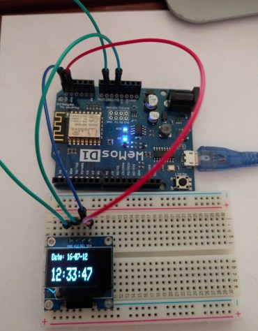
The second one, which runs on ESP8266, implements a clock:
It depends on rAdafruitGFX library: https://www.b4x.com/android/forum/threads/radafruitgfx.68904/
It allows drawing graphics and text on supported monochrome OLED modules.
I've tested it with an I2C module. You need to pass the I2C address (default is 0x3c) and an available pin (4) in the example.
The GFX field from the SSD object is used for the drawings.
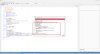
B4X:
ssd.GFX.DrawCircle(px, py, radius, ssd.BLACK, True)There are two examples attached.
The first is a bouncing ball:
The second one, which runs on ESP8266, implements a clock:
Attachments
Last edited: